11
11
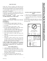
P104E** Units Require
• Wire
• Wire cutters
• Wire terminal crimpers
• Terminals
• Fuse/circuit breaker
SPECIFICA
TIONS
FOR WIRING
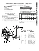
CONVERTING PHII TO ELECTRIC OPERATION
ORDER PART NUMBER P104E**
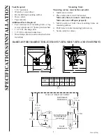
Item# Part# Description
1
1131**
Gearbox and Motor
2
1134
Gearbox Connecting Rod
3
1136
Roller for Gearbox Assy
4
1137
Roller Washer
5
F360
Screw for Roller (3)
6
1135
Link for Gearbox Assy
7
F359
Gearbox Mounting Screw
8
1138
Gearbox Bracket
9
F149VT
Socket Set Screw
10
1119A
Screw, 1/4-20 x 1/2 Hex (4)
Not Shown 1118
Washer, 1/4 Ext. Tooth (4)
11
1115
Bolt, 3/8-16 x 1 1/2 Hex
12
1115A
Nut, 3/8-16 Hex Jam, S/S
13
PRS
Momentary Flush Switch
(includes face plate)
** Specify Voltage: 12, 24
P104E** Units Include
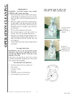
RETURNING ELECTRICAL TO
MANUAL OPERATION
WARNING: Secure circuit breaker in "OFF" position
before proceeding.
1. Remove arm bolt and nut (#1115 and #1115A) from
the top of the connecting rod (#1134).
2. Displace connecting rod (#1134) from track.
3. Insert the handle (#1208W) and cotter pin (#1210A).
To return to electrical operation, reverse procedure.
12
11
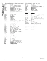
UNIT’S
VOLTAGE
12 12 (6.0) 10 (6.0) 10 (10.0) 8 (16.0) 8 (16.0) 6 (16.0) 6 (25.0)
24 16 (1.5) 16 (2.5) 14 (4.0) 12 (4.0) 12 (6.0) 10 (6.0) 10 (10.0)
Nominal Voltage (Volts DC)
12V
24V
Amperage Draw @ Nominal Voltage
15
8
Circuit Breaker/Fuse Size (Amps)
20
15
Electrical
SPECIFICATIONS
Minimum recommended conductor wire AWG (mm
2
)
for 3% voltage drop
10' (3.1) 15' (4.6) 20' (6.1) 25' (7.2) 30' (9.2) 40' (12.2) 50' (15.2)
Distance from source to unit and back to source [feet (m)]
Wire Sizes
NOTE: Recommended conductor sizes based on 105C rated insulation.
Refer to ABYC Standards for other insulation ratings.
NOTE: Never mount conversion kit where it may
be subject to shower spray or other sources of
external water.
L584v0222jlc


