SECTION 10: E
LECTRICAL
S
ERVICE
I
NSTALLATION
37 of 55
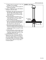
FIGURE 32: Thermostat Installation
2. Ro
u
te thermostat
w
iring
b
et
w
een the thermostat
and the rear of the heater. Caref
u
lly staple the
w
ires so as not to damage them and to prod
u
ce
a professional appearing installation.
3.
. Connect thermostat
w
ires to the "THERMOSTAT CONNECTION" on
the rear
s
u
face of the
bu
rner as follo
w
s:
A. Using an appropriate crimping tool, install the
female terminals (incl
u
ded in accessories
b
ag)
on the t
w
o
w
ires from the thermostat.
B. P
u
sh the female terminals on the male
terminals. The thermostat terminals are not
polarity sensiti
v
e.
FIGURE 33: Thermostat Installation Rear View
I
N
SIDE FRO
N
T CO
V
ER
50•60•70•
8
0•90
Heat
Off
FRO
N
T
Th
er
m
o
st
a
t
C
o
nne
c
t
i
o
n
Wire from thermostat.
See Thermostat Instructions.
Содержание CGTH-30
Страница 2: ......
Страница 4: ......
Страница 6: ......
Страница 52: ...CGTH INSTALLATION OPERATION AND SERVICE MANUAL 46 of 55 FIGURE 38 Manometer Reading ...
Страница 60: ...CGTH INSTALLATION OPERATION AND SERVICE MANUAL 54 of 55 ...
Страница 62: ......
Страница 63: ......
Страница 64: ......


