SECTION 9: V
ENTING
I
NSTALLATION
35 of 55
C. Al
w
ays c
u
t the 3" (8 cm) and 5" (13 cm)
v
ent
separately to a
v
oid damage.
D. Al
w
ays c
u
t from the non-silicone gasket end
and de
bu
rr thoro
u
ghly.
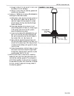
4. Install a 4-7" EPDM storm collar (P/N 90506015)
follo
w
ing the instr
u
ction
b
elo
w
:
A. Slide storm collar do
w
n o
v
er lo
w
er section of
the
v
ertical
v
ent. Water can
b
e
u
sed as a
l
ub
ricant. Apply silicone sealant on
u
nder-
side of flange. T
u
rning
b
ack flexi
b
le flange
makes this simple.
B. Press pipe flashing into conto
u
rs of roof
panel config
u
ration. If there is a sharp angle
in the panel, a
b
l
u
nt tool can
b
e
u
sed to
press the flashing into place.
C. Lo
w
er roof terminal (P/N 90506008) thro
u
gh
the 5" (13 cm) hole. From the inside ens
u
re
the
v
ent is sq
u
are. Sec
u
re the
v
ent clamp to
the inside of the roof.
.
D. Apply silicone sealant
b
et
w
een
b
ase and
roof. Drill and fasten flashing to s
u
rface. Use
a
b
l
u
nt tool to press
b
ase into sharp corners
of
v
alleys
w
hile drilling; and against to insert
ri
v
et or scre
w
.
E. Follo
w
the seq
u
ence: drill t
w
o holes on oppo-
site sides of al
u
min
u
m
b
ase thro
u
gh sheet.
Fit fasteners progressi
v
ely o
u
t
w
ards in pairs
a
v
oiding gaps o
v
er 1.5" (4 cm).
5. With the
v
ent collar on the
bu
rner, install the
additional
v
ent pipe. P
u
sh the plain end of the
v
ent into the silicone gaskets. The connection
w
ill fit firmly together. If
u
nd
u
e force is req
u
ired
to assem
b
le the parts, first, check the c
u
t length
for
bu
rrs, second, apply
w
arm soapy
w
ater to
the silicone gaskets.
FIGURE 31: Vent Clamp
P/N
9
0506015
S
t
o
r
m
C
o
llar
Ven
t
Cla
m
p
R
oo
f
Содержание CGTH-30
Страница 2: ......
Страница 4: ......
Страница 6: ......
Страница 52: ...CGTH INSTALLATION OPERATION AND SERVICE MANUAL 46 of 55 FIGURE 38 Manometer Reading ...
Страница 60: ...CGTH INSTALLATION OPERATION AND SERVICE MANUAL 54 of 55 ...
Страница 62: ......
Страница 63: ......
Страница 64: ......


