Concepts and features
R&S
®
ZNB/ZNBT
140
User Manual 1173.9163.02 ─ 62
●
c: Common mode (for balanced ports)
The notation of a general S-parameter is S
<mout><min><out><in>
, where <mout> and <min>
denote the output and input port modes, <out> and <in> denote the output and input
port numbers.
Meaning of 2-port mixed mode S-parameters
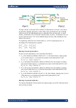
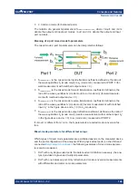
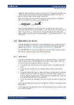
The mixed mode 2-port S-parameters can be interpreted as follows:
●
S
<mout><min>11
is the mixed mode input reflection coefficient, defined as the ratio of
the wave quantities b
1
(mode mout) to a
1
(mode min), measured at PORT 1 (for-
ward measurement with matched output and a
2
= 0).
●
S
<mout><min>21
is the mixed mode forward transmission coefficient, defined as the
ratio of the wave quantities b
2
(mode mout) to a
1
(mode min) (forward measure-
ment with matched output and a
2
= 0).
●
S
<mout><min>12
is the mixed mode reverse transmission coefficient, defined as the
ratio of the wave quantities b
1
(mode mout) (reverse measurement with matched
input, b
1
' in the figure above and a
1
= 0) to a
2
(mode min).
●
S
<mout><min>22
is the mixed mode output reflection coefficient, defined as the ratio of
the wave quantities b
2
(mode mout) (reverse measurement with matched input, b
2
'
in the figure above and a
1
= 0) to a
2
(mode min), measured at PORT 2.
If <mout> is different from <min>, the S-parameters are called mode conversion fac-
tors.
Mixed-mode parameters for different test setups
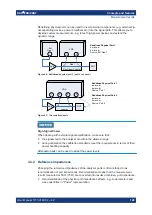
Which types of mixed mode parameter are available depends on the measured device
and the port configuration of the analyzer. With 4 physical test ports (on the VNA and
connected
), the following examples of mixed mode parame-
ters can be measured.
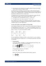
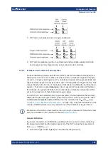
1. DUT with only single-ended ports: No balanced port definition necessary, the ana-
lyzer provides single-ended multiport parameters.
2. DUT with one balanced port: Only reflection and mode conversion measurements
with differential and common mode parameters.
Measurement results

