background image

Operating the Instrument

R&S

®

 ZNA

29

Getting Started 1178.6456.02 ─ 05

5


Operating the Instrument

The following sections describe the basics of manual operation, i.e. how to access
instrument functions and settings via the analyzer GUI. Manual operation is particularly
useful for getting to know the instrument and for trouble shooting.

Manual and remote control of the instrument

Manual control of the R&S


ZNA is possible either via its touchscreen (without using a

mouse and/or keyboard), via locally connected m mouse + keyboard (see

Chapter 3.9, "Connecting External Accessories"

on page 16), or via Remote Desktop

(see also 

Chapter 7.3, "Remote Operation in a LAN"

on page 66). Alternatively it can

be remote-controlled via the GPIB interface or a LAN connection.

To their full extent, manual operation and remote control are described in the GUI Ref-
erence and Command Reference chapters of the user manual, respectively. GUI func-
tions and related remote commands are linked bidirectionally. Background information
is provided in the Concepts and Features chapter of the user manual.

5.1


Manual Operation

The analyzer functions are accessible via several tabbed softtools, each presenting
related functions and settings. The function keys on the control window open the most
frequently used softtools (see 

Chapter 4.1.1.2, "Control Window: Function Keys"

,

on page 22).

Manual operation via function keys and softtools provides touch-friendly access to the
instrument functions and settings, avoiding complicated menu structures and long
operating sequences. In general, this approach is recommended. However, sometimes
the toolbar or an object's context menu can offer a shortcut. As a full-fledged alterna-
tive for manual operation via mouse and keyboard, also the menu bar provides access
to all instrument functions and settings.

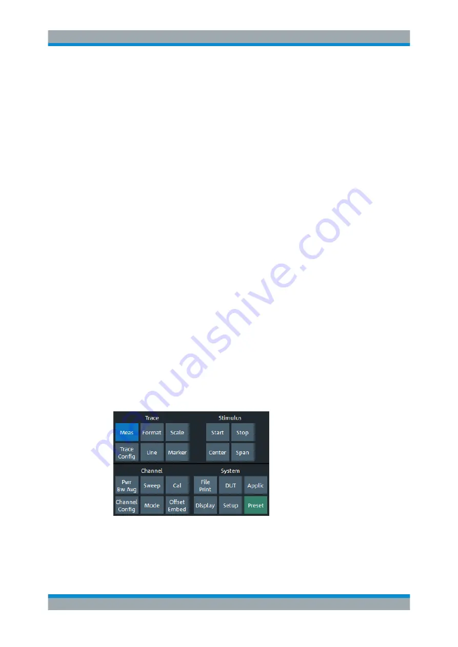
Figure 5-1: Function Keys

Manual Operation

Содержание ZNA Series

Страница 1: ...R S ZNA Vector Network Analyzers Getting Started Getting Started Version 05 1178645602 2...

Страница 2: ...z 4 test ports 2 92 mm order no 1332 4500 44 R S ZNA43 10 MHz to 43 5 GHz 2 test ports 2 4 mm order no 1332 4500 43 R S ZNA43 10 MHz to 43 5 GHz 4 test ports 2 4 mm order no 1332 4500 45 2019 Rohde Sc...

Страница 3: ...2 1 Typographical Conventions 9 2 2 2 Conventions for Procedure Descriptions 10 2 2 3 Notes on Screenshots 10 3 Putting the Analyzer into Operation 11 3 1 Unpacking and Checking the Instrument 11 3 2...

Страница 4: ...ructure 36 5 2 6 Hardkey Panel 37 5 2 7 Status Bar 38 5 3 Touchscreen Gestures 38 5 4 Working with Dialogs 41 5 5 Handling Diagrams Traces and Markers 42 5 5 1 Adding New Traces and Diagrams 42 5 5 2...

Страница 5: ...Sweep Range and Other Parameters 57 6 1 3 Calibrating the Instrument 58 6 1 4 Evaluating Data 61 6 1 5 Saving and Printing Data 62 6 2 Reflection S Parameter Measurement 63 7 Administrative Tasks 65...

Страница 6: ...Contents R S ZNA 6 Getting Started 1178 6456 02 05...

Страница 7: ...and laboratory environ ments Use the R S ZNA only for its designated purpose Observe the operating con ditions and performance limits stated in the data sheet Where do I find safety information Safety...

Страница 8: ...nual contains the description of all instrument modes and functions It also provides an introduction to remote control a complete description of the remote control commands with programming examples a...

Страница 9: ...d deals with the specific char acteristics See https www rohde schwarz com brochure datasheet ZNA 2 1 7 Release Notes and Open Source Acknowledgment OSA The release notes list new features improvement...

Страница 10: ...rm the same task In this case the procedure using the touchscreen is described Any elements that can be activated by touching can also be clicked using an addition ally connected mouse The alternative...

Страница 11: ...the safety instructions in the following sections In particular Do not open the instrument casing Risk of instrument damage due to inappropriate operating conditions An unsuitable operating site or te...

Страница 12: ...yzer is designed for use under laboratory conditions either on a bench top or in a rack Notice the general ambient conditions at the operating site described under Risk of instrument damage due to ina...

Страница 13: ...19 racks using the adapter R S ZZA KN6 order number 1332 4498 02 Proceed according to the mounting instructions supplied with the rack adapter Risk of instrument damage due to insufficient airflow in...

Страница 14: ...V to 240 V at 50 Hz to 60 Hz A line frequency of 400 Hz is also supported The mains connector is located in the upper part of the rear panel see Chapter 4 2 Rear Panel on page 26 Connect the network...

Страница 15: ...ll run ning you lose the current settings Moreover loss of program data cannot be excluded if the application is terminated improperly The AC power switch can be permanently on It is recommendable how...

Страница 16: ...controlled via USB External monitor keyboard and mouse are not required for local operation The R S ZNA can be fully controlled by tapping the touchscreen 3 9 1 Connecting a Monitor A standard monito...

Страница 17: ...System File Print Print the analyzer checks whether a printer is connected and turned on and whether the appropriate printer driver is installed Printer driver installation If necessary the printer d...

Страница 18: ...Remote Settings softtool tab 3 9 6 Connecting a USB Cable for Remote Control The R S ZNA can also be remote controlled via USB To prepare for remote control operation connect a suitable USB 2 0 or 3...

Страница 19: ...Putting the Analyzer into Operation R S ZNA 19 Getting Started 1178 6456 02 05 A software update restores the original shortcut properties Minimizing the VNA Application...

Страница 20: ...R S ZNA consists of a large scale capacitive touchscreen and the test port area below it Brief explanations on the controls and connectors can be found on the next pages Two port and four port network...

Страница 21: ...r receives no command for a selectable period of time The display is switched on again when the touchscreen is touched 4 1 1 1 Application Window The left part of the touchscreen is reserved for the a...

Страница 22: ...a trace configure their properties and select the for mat of the numerical readout Markers can also be used to locate specific points on the trace define the sweep range and scale the diagram The Cha...

Страница 23: ...rs The appearance of the panel depends on the data type of the setting selected in the Application Window Figure 4 1 Data Entry Panel left numeric value right string value While most of the keys have...

Страница 24: ...and as inputs for the mea sured RF signals from the DUT response signals With a single test port it is possible to generate a stimulus signal and measure the response signal in reflection For a measu...

Страница 25: ...f Out Meas Out The direct generator receiver access can be used to insert external components exter nal signal separating devices power amplifiers extension units etc into the signal path This feature...

Страница 26: ...isplay Port External monitor connector DisplayPort see Chapter 3 9 1 Connecting a Monitor on page 16 3 DVI Digital only External monitor connector DVI D see Chapter 3 9 1 Connecting a Monitor on page...

Страница 27: ...signals LV TTL 3 3 V 5 V tolerant 15 Ground connector The ground connector provides the ground of the analyzer s supply voltage Use this con nector for ESD protection see Instrument damage caused by e...

Страница 28: ...nt RF Front End RFFE interfaces and 10 General Purpose Input Output GPIO pins on a single connector 25 pins female The RFFE interfaces meet the MIPI Alliance System Power Management Interface Specifi...

Страница 29: ...d in the GUI Ref erence and Command Reference chapters of the user manual respectively GUI func tions and related remote commands are linked bidirectionally Background information is provided in the C...

Страница 30: ...fixed You can display or hide most elements You can also drag and drop traces and info fields Using the Touchscreen To access an instrument function 1 Press a virtual key e g the Meas key in the Trace...

Страница 31: ...1 The diagram immediately reflects your selection The active trace shows the mea surement results for the selected measured quantity A control element with three dots e g System Setup Setup System Con...

Страница 32: ...y Converting Wave a1 Src Port 1 The diagram immediately reflects your selection The active trace shows the mea surement results for the selected measured quantity At the same time the related softtool...

Страница 33: ...to the previous method Using the context menus of certain display objects for important actions in the context of this object Using the icons in the toolbar above the diagram area for frequent global...

Страница 34: ...m area Add a new marker to the active diagram single tap similar to Trace Marker Markers Mkr i or to an arbitrary one drag drop the Mkr icon Delete the active trace single tap the trash icon or an arb...

Страница 35: ...while others open additional dialogs button label ends with 5 2 4 Menu Bar All analyzer functions are arranged in drop down menus The menu bar is located across the bottom of the diagram As in any Win...

Страница 36: ...s functions that can be used to return to a defined instrument state reverse operations access service functions and define various system related settings The Help menu provides assistance with the n...

Страница 37: ...Chapter 4 1 1 2 Control Window Function Keys on page 22 The Hard Key panel is particularly useful if the analyzer is controlled from an external monitor or Remote Desktop For the R S ZNA it is hidden...

Страница 38: ...connection has been established a red symbol indicates that no LAN cable is connected the current date and time Figure 5 3 R S ZNA with redefined physical ports The progress bar shows a moving color g...

Страница 39: ...the displayed area of the table or diagram to show results that were previously out of view Figure 5 5 Dragging Spreading and pinching two fingers Move two fingers apart on the display spread or move...

Страница 40: ...ollowing touch actions correspond to mouse actions Table 5 1 Correlation of mouse and touch actions Mouse operation Touch operation Click Tap Double click Double tap Click and hold Touch and hold Righ...

Страница 41: ...The title bar of each dialog contains some convenience functions Use the Dialog Transparency function to make the display elements behind the dialog visible Note The Dialog Transparency is a global s...

Страница 42: ...s and screen elements 5 5 1 Adding New Traces and Diagrams A new trace is required if you want to measure and display an additional quantity Typical scenario The transmission coefficient S21 is measur...

Страница 43: ...for the selected S parameter Alternative control elements To measure a different quantity select Trace Meas Drag and drop a softkey repre senting a measured quantity to create a trace Or simply select...

Страница 44: ...eps Active trace alternative control elements The trace line of the active trace in the upper part of the diagram is highlighted If the diagram contains several traces first activate the target trace...

Страница 45: ...nction If you happen to delete a display element unintentionally you can restore it using the Undo toolbar icon 5 5 4 Using Drag and Drop You can drag and drop many of the R S ZNA s control and displa...

Страница 46: ...ard procedure known from other Windows applications However there are various other ways to enter data 5 6 1 Dual Window Mode vs Single Window Mode In dual window mode default both the application win...

Страница 47: ...n with touchscreen or mouse 1 Double tap double click a numeric input field in a dialog or on a softtool to open the numeric editor 2 Use the buttons in the numeric keypad to compose the numeric input...

Страница 48: ...f the control window is adjusted accordingly Hence in dual window mode there is typically no need to open the on screen keyboard For the following procedure we assume single window mode 1 Activate a c...

Страница 49: ...ange Choose the method that is most convenient for you 5 7 1 Using the Graphical Zoom The graphical zoom function magnifies a rectangular portion of the diagram zoom win dow to fill the entire diagram...

Страница 50: ...shows the selected rectangle scaled in both horizontal and verti cal direction In general the zoom window covers only a part of the sweep range the horizontal distance between the sweep points increa...

Страница 51: ...The upper part of the diagram then shows a small version of the unzoomed diagram You can move the zoomed part of the trace by moving the rectangular area in the overview To zoom the stimulus range ke...

Страница 52: ...orks for radial diagrams Changing the Scale Div modifies the value of the vertical or radial diagram divi sions and thus the entire range of response values displayed The Scale Div and the Ref Value a...

Страница 53: ...methods Locate it on the Trace Scale Scale Values softtool tab Tap and hold with a mouse right click the scale section in the trace info and select the parameter from the context menu Select the param...

Страница 54: ...normal marker e g the marker Mkr 1 default label M1 2 Place M1 to a particular trace point e g use the Marker Search functions to locate a maximum or minimum on the trace 3 Select Trace Marker Set by...

Страница 55: ...d 1178 6456 02 05 The System Display Config softtool tab defines optional display elements for the interior of the diagrams Use the context menu of the diagram the System Display key or the Display me...

Страница 56: ...t The trace settings allow you to select the measured quantities and display formats depending on what you want to learn from the data A minimum of two ana lyzer test ports are required for transmissi...

Страница 57: ...ore a well defined instrument state The analyzer is now set to its default state The default measured quantity is the transmission S parameter S21 Select Trace Trace Config and use the control element...

Страница 58: ...requency input field enter the highest frequency you want to mea sure e g 2 5 GHz 3 Select Trace Scale Scale Values and activate the Auto Scale Trace func tion The analyzer adjusts the scale of the di...

Страница 59: ...calibration wizard calibration is a straightforward guided proc ess 1 Replace the DUT by the Through standard of your calibration kit 2 Select Channel Cal Start Manual to open the Calibration Setting...

Страница 60: ...ion dock widget indicates the standard measurements that make up a Trans Norm calibration Select Through mm to initiate the measurement of the connected Through stan dard Measuring the isolation betwe...

Страница 61: ...Data The analyzer provides various tools to optimize the display and analyze the measure ment data For instance you can use markers to determine maxima and minima on the trace and change the display...

Страница 62: ...s if you were working on a standard PC Moreover you can export your trace data to an ASCII file and reuse it in a later session or in an external application Data transfer is made easier if external a...

Страница 63: ...an be restored in a later session 6 2 Reflection S Parameter Measurement In a reflection measurement the analyzer transmits a stimulus signal to the input port of the device under test DUT and measure...

Страница 64: ...select an appropriate type A full n port calibration TOSM UOSM TNA corrects the system errors for all transmission and reflection S parameters Some of the trace formats are particularly suited for ref...

Страница 65: ...by Rohde Schwarz for use on the instrument must be executed All necessary settings can be accessed from the Windows Start menu in particular from the Control Panel To open the Start menu press the Win...

Страница 66: ...e from the Windows Explorer Follow the instructions of the setup wizard Setup files can be reinstalled The default name of the internal drive is C External storage devices are automatically mapped to...

Страница 67: ...t to use alternate TCP IP configuration the addresses must be set manually By default the analyzer is configured to use dynamic TCP IP configuration and obtain all address information automatically Th...

Страница 68: ...t Properties and confirm the user account control message depending on your current user account If your current account is an administrator account select Yes If your account is an account with stand...

Страница 69: ...es of the analyzer At the R S ZNA by default remote connections are enabled using a local group policy and remote access is granted to users instrument and administrator For detailed information about...

Страница 70: ...with other hosts in the LAN you have to allow File and Printer Sharing To change the firewall settings proceed as follows 1 Access the operating system by pressing the Windows key on the external key...

Страница 71: ...olvents can damage the front panel labeling plastic parts or screens for example Never use cleaning agents to clean the outside of the instrument Use a soft dry lint free dust cloth instead Risk of in...

Страница 72: ...erature range quoted in the data sheet When it is stored for a longer period of time the unit must be protected against dust If possible use the original packing when the instrument is to be transport...

Страница 73: ...Setup softtool tab Finally our customer support centers are there to assist you in solving any problems with your network analyzer The required troubleshooting information can also be generated in the...

Страница 74: ...gger Connector 26 External Handler IO Connector 26 F Factory calibration 66 Firewall 70 Firmware Setup file 66 Firmware update Update 66 Front panel 20 Front panel keys 29 Function keys 22 Channel sec...

Страница 75: ...ce Clock In Out Connectors 26 Reference position 52 Reference value 52 Reflection measurement example 63 Release notes 9 Remote desktop 69 Removable System Drive 26 RFFE GPIO Interface 27 S Safety ins...

Отзывы: