


Interfaces and Connectors
R&S
®
DVMS1
23
Getting Started 2113.7619.02 ─ 12
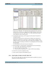
Figure 3-7: S/S2 receiver module
The status of the connectors is indicated by LEDs. Before showing a new state, each
LED holds the current state for at least one second, if the current state is not "off" or
"flashing".
To help locating a connector socket, you can let its status LED flash blue ("Instrument
Configuration" dialog, "Signal Interfaces" tab, see the user manual or help system).
RF IN
This F socket (female connector
@
DVMS) is used to feed in an RF signal conforming
to the DVB
‑
S (EN 300421), DVB
‑
S2 (EN 302307) or DIRECTV legacy modulation
standards.
An LED indicates the RF IN status:
●
LED off: Input is not used for monitoring.
●
LED green: Input is used for monitoring. Synchronization state is valid for both RF
signal and related transport stream.
●
LED yellow: Input is used for monitoring but synchronization cannot be achieved.
TS IN
This BNC socket is used to feed in an MPEG2 transport stream signal conforming to
the DVB
‑
ASI (EN 50083
‑
9 (2002)) or SMPTE (SMPTE 310M) interface standards.
An LED indicates the TS IN status:
●
LED off: Input is not used for monitoring.
●
LED green: Input is used for monitoring. Synchronization state is valid for the trans-
port stream signal.
●
LED yellow: Input is used for monitoring but synchronization cannot be achieved.
TS OUT
This BNC socket provides an MPEG2 transport stream signal conforming to the
DVB
‑
ASI (EN 50083
‑
9 (2002)) interface standard.
The interface is used as a loop output for a transport stream signal from the [RF In] or
[TS In] input (see above).
To select the input, in the toolbar, click "Instrument Configuration" and then select "Sig-
nal Interface". See the user manual or help system.
Rear Panel