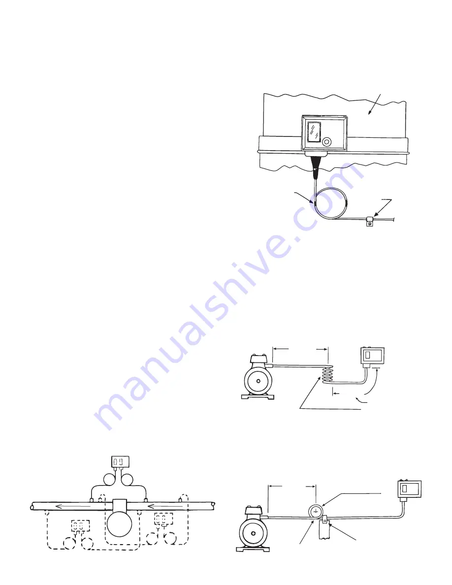
CONTROL BODY MOUNTING
Select a location that will permit proper capillary routing. It is
important not to twist or strain the control body as shifting of the
calibration may result.
RANCO pressure controls can be mounted in any position,
either vertically or horizontally, without affecting performance. The
control can be mounted on an existing bracket, on the bracket
provided, or can be flush-mounted without a bracket. Whichever
method is selected, use only the mounting holes provided; no
other holes are to be added to the control frame.
1. Secure the control to a bracket with the 10-32 x 3/16
screws
by using the two tapped holes in the back of the control.
If other mounting screws are used, they must not
protrude into the control more than 1/8” to avoid
damage.
2. When using the angle bracket, the control can be mounted to
the compressor or any flat surface by using two or more of
the four slotted holes in the base of the angle bracket.
3. When flush mounting the control, use the .20 inch holes in
the back of the control frame. Access can be gained by
removing the front cover an securing
the control body to a wall or any flat surface.
Mounting to an uneven surface may cause improper
control operation.
CAPILLARY CARE AND MOUNTING
Compressors vibrate. Copper work-hardens and fractures when
flexed beyond its physical limits. Combine these two factors
and broken capillaries can result. Breakage can be prevented by
proper installation practices.
1. Minimizes the number of times the capillary is bent. Each
time it is rebent, it work-hardens making it more susceptible
to breakage.
2. Avoid sharp bends, kinks, strains or pinch marks in the
capillary. Never allow the capillary to rest against sharp
edges or rub against metal surfaces where it can be
damaged by friction.
3. The capillary should be straight within 4 inches of the
pressure connection so the pulsations do not work-harden
the capillary.
4. Purge all tubing and lines before connecting pressure
controls.
5. Route the capillary so that it will be safe-draining to minimize
PREFERRED
H.P.
L.P.
No
Alternate
oil logging.
6. When the control is mounted directly on the compressor, the
capillary must be secured to the compressor so that ever
thing moves together. If the capillary or control is shaking or
vibrating against the compressor vibration, work-hardening
Plastic or
Rubber Lined
Clamp
Coils can be taped
or tied. See
notes 8, 9 & 10
Compressor
COMPRESSOR MOUNTING
of the capillary may occur, leading to eventual failure.
7. When the control body is mounted remote from the
compressor and the pressure connections are on the
compressor, vibration coils must be used between the
compressor and the mounted control. The coils should not
touch. A section of rubber pipe insulation inserted into the
vibration coils and secured with silicone adhesive will keep
the coils separated, yet allow them to absorb vibration.
The capillary between the vibration coils and the control body
should be secured to a stationary member when that distance
3” to 6”
If this distance is more
than 6”, the tubing
should be clamped
as shown below.
Min. of 2 Coils
2 to 3 Inch
Diameter Coils
12” to 18”
Control
Coils Should Not
Touch
Compressor
REMOTE MOUNTING
exceeds 6 inches.
The capillary between the vibration coils and the control body
should be secured to a stationary member when that distance
exceeds 6 inches.
12” Approx
Min. of 2 Coils
2 to 3 Inch Dia.
Coils
Clamp Tube to
Stationary Member
2 or More Coils of Tubing On
Compressor Side Clamp
Coils Should Not
Touch
Compressor
Control
REMOTE MOUNTING
2


