background image

49

English 

RAIS/

attika

 - User manual for Q-Tee II Gas / Q-Tee II C Gas

Содержание Q-Tee II GAS

Страница 1: ... G S A N L E I T U N G U S E R M A N U A L M A N U E L D U T I L I S AT E U R B R U K E RV E I L E D N I N G B R U K S A N V I S N I N G K Ä Y T T Ö O H J E G E B R U I K E R S H A N D L E I D I N G POSITIV Q Te e I I G A S Q Te e I I C G A S ...

Страница 2: ......

Страница 3: ...3P 37 I3P 50 I3B P 30 I3B P 50 HEAT INPUT Gross KW BURNER PRESSURE Hot mbar COUNTRY of DESTINATION G20 20 mbar G20 20 mbar G20 G25 20 25 mbar G25 20 mbar G20 G25 3 25 mbar G30 G31 28 37 mbar G31 30 mbar G31 37 mbar G31 50 mbar G30 G31 30 mbar G30 G31 50 mbar 9 1 9 1 9 1 8 4 7 5 8 5 8 7 8 8 8 8 36 27 36 36 28 27 36 16 6 13 4 13 2 16 4 13 2 13 2 AT BG CH CZ DK EE ES FI GB GR HR IE IT LT LV NO PT RO ...

Страница 4: ...ve has been tested and certificated for use with natural gas LPG and bio propane Biopropane can be used if the stove is adjusted for use with LPG liquid petroleum gas see rating plate under PROPANE This manual covers the following models The stove is HOT during operation Wear gloves when opera ting the stove Do not operate the stove with an open door damaged glass worn or damaged seals Caution the...

Страница 5: ...OR NON FLAMMABLE WALL 26 CHIMNEY FLUE 27 LOCATION OF CHIMNEY TERMINALS 28 HORIZONTAL WALL TERMINAL TYPE C11 29 VERTICAL ROOF TERMINAL C31 30 FITTING OF SECONDARY BURNER 31 Arrangement of Embers and Logs 32 START UP BATTERIES 37 SETTING UP THE ELECTRONIC CODE 39 COMMISSIONING 40 INITIAL IGNITION 42 USER INSTRUCTIONS REMOTE CONTROL 43 USING STOVE WITHOUT REMOTE CONTROL 49 SERVICE SERVICE 51 CLEANING...

Страница 6: ... and benefit from your new stove it is important that you read the manual thoroughly before it is installed and put to use For the purpose of the guarantee and all contact regarding the stove in general it is important that you can state the stove s production number We therefore recommend that you write down the number in the form below The production number can be found at the bottom of the stov...

Страница 7: ...damage due to overfiring damage due to external influences and the use of unsuitable fuels failure to comply with statutory or recommended installation instructions and in the event the user s own modifications of the stove lack of servicing and care the stove must be serviced annually In the event of damage please contact your dealer In the event of claims under the guarantee we will decide how t...

Страница 8: ... gas temperature C G20 I2H I2E 210 210 Intertek Testing Certification Ltd Registered office Academy Place 1 to 9 Brook Street Brentwood Essex CM14 5NQ United Kingdom Registered No 3272281 England VAT No GB 672 7639 96 011 T 44 1277 223 400 F 44 1277 223 127 Distances template See scale drawings at back of the manual I Distance from floor to flue outlet top J Distance from floor to centre flue outl...

Страница 9: ... later use The manual is necessary when the stove is to be serviced Ensure that the chimney terminal is not blocked in any way and is free of vegetation in the form of trees bushes etc and that objects are not resting against the chimney s terminal or the protection around the terminal The door glass should always be cleaned before the stove is turned on and fingerprints wiped as these can be burn...

Страница 10: ...n tap and the gas meter Ventilate the room by opening windows and doors do not use electrical appliances in the vicinity of the stove Or operate any electrical switches The gas supply must not be switch on until a Gas Safe Registered engi neer has checked the system and deem it as being safe English RAIS attika User manual for Q Tee II Gas Q Tee II C Gas ...

Страница 11: ...and servicing the stove Gas connection The inlet supply pipe has an external diameter of Ø8mm An isolation tap must be fitted Ventilation This stove has a sealed combustion chamber and is intended for a bal anced draught There is therefore no need for an extra air supply It is recommended that sufficient fresh air is supplied to the room to maintain a comfortable environment This stove may be inst...

Страница 12: ...ted in the following sections with regard to installation risk of fire When you choose where you wish to position your stove you should consider the heat distribution to the other rooms Then you will get the maximum possible pleasure from your stove Inspect the stove for defects upon receipt Changing the chimney connection The stove is supplied ready for a top outlet but can be changed to a rear o...

Страница 13: ...nd remove it 4 Unscrew the outer cover plate at the rear of the stove and move it to the upper sur face of the stove 5 To open the door a 10mm open ended spanner is re quired to turn the two catches at the top and bottom of the door 6 The secondary burners are removed by lifting them verti cally up and out English RAIS attika User manual for Q Tee II Gas Q Tee II C Gas ...

Страница 14: ...c logs are fitted remove these 10 The internal cover plate is now fitted to the un derside of the top plate as shown It is vital that this plate fits and seals correctly 11 Fit the connecting piec es where the cover plates were and replace the back plate logs and burners English RAIS attika User manual for Q Tee II Gas Q Tee II C Gas ...

Страница 15: ...t only be carried out by a Gas Safe Registered engineer Conversion kit Use article number 3713595 This set contains 4 new injectors suitable for propane LPG gas The injectors for the secondary burners for LPG are marked 100 The injectors for the second ary burners for natural gas are marked 260 English RAIS attika User manual for Q Tee II Gas Q Tee II C Gas ...

Страница 16: ...PG is marked 27 The injector for the pilot light for natural gas is marked 32 The injector for the main burner for LPG is marked 80 The injector for the main burner for nat ural gas is marked 120 English RAIS attika User manual for Q Tee II Gas Q Tee II C Gas ...

Страница 17: ...tled to gain access to the injectors Do this in the following manner Lift the perforated plate up and out of the stove Loosen the four screws holding the gas unit in place English RAIS attika User manual for Q Tee II Gas Q Tee II C Gas ...

Страница 18: ...unscrew the injector Fit the LPG injector and tighten the lock nut Finally re tighten the coupling Once the gas unit has been dismounted replace the four injectors and adjust the three air intakes Now the gas unit can be lifted out carefully by tilting and rotating the unit a little English RAIS attika User manual for Q Tee II Gas Q Tee II C Gas ...

Страница 19: ...it the LPG injector and tighten the lock nut Finally re tighten the coupling Replace the injector for the pilot light by loosening the coupling and carefully pull ing the pipe out Note The small pilot light injector should now fall out and can be replaced with the LPG injector English RAIS attika User manual for Q Tee II Gas Q Tee II C Gas ...

Страница 20: ...n the vertical pipe are now open the small one at the rear and the large one at the front Small hole at the rear Large hole at the front The air intake to the main burner is adjust ed for LPG configuration by loosening the two nuts and pushing the plate all the way towards the burner The hole fully open English RAIS attika User manual for Q Tee II Gas Q Tee II C Gas ...

Страница 21: ...hen the stove is config ured for LPG The gas unit is reassembled using the four screws Replace the perforated plate and fully assemble the stove See Section Assembly of secondary burn ers English RAIS attika User manual for Q Tee II Gas Q Tee II C Gas ...

Страница 22: ...r the local building authorities It must be ensured that flammable objects e g furniture are not positioned closer than the distances stated in the following tables risk of fire Normal installation at right angle Q Tee II Gas A Furniture distance min 700 mm Distance to flammable material min D rear wall 50 mm E to side to wall 250 mm Norwegian Firewall D rear wall 50 mm E to side to wall 225 mm O ...

Страница 23: ... 310 Normal installation at right angle Q Tee II C Gas A Furniture distance min 700 mm Distance to flammable material min D rear wall 50 mm E to side to wall 250 mm Norwegian Firewall D rear wall 50 mm E to side to wall 225 mm O Extent of firewall to the side 75 mm P Extent of firewall to front 500 mm English RAIS attika User manual for Q Tee II Gas Q Tee II C Gas ...

Страница 24: ...00 76 460 149 291 309 309 D 50 D 50 O 75 D 50 E 225 P 500 309 309 Corner installation 45 Q Tee II Gas A Furniture distance min 700 mm Distance to flammable material min D rear wall 50 mm English RAIS attika User manual for Q Tee II Gas Q Tee II C Gas ...

Страница 25: ...00 76 460 179 330 310 310 D 50 D 50 O 7 D 50 E 225 P 500 310 310 English RAIS attika User manual for Q Tee II Gas Q Tee II C Gas Corner installation 45 Q Tee II C Gas A Furniture distance min 700 mm Distance to flammable material min D rear wall 50 mm ...

Страница 26: ...l to allow service and installation Where the outlet is to the rear there should however be space for a measuring connection piece for combustion control Normal installation at right angle Q Tee II Gas Q Tee II C Gas Corner installation 45 Q Tee II Gas Q Tee II C Gas English RAIS attika User manual for Q Tee II Gas Q Tee II C Gas ...

Страница 27: ...ng locking bands or suitable rivets screws If possible a measuring connection piece should be installed on the flue in the same room as the stove so that a combustion check can be performed Where the terminal is accessible this is unnecessary Ensure the flue terminal position complies with Building Regulations Approved Docu ment J BS EN 5440 1 and the label in these instructions Ensure that flue p...

Страница 28: ... 300 H From an internal or external corner 600 I Overground roof or balcony level 300 J From a surface facing the terminal 600 K From a terminal facing the terminal 600 L From an opening in carport e g door window into the dwelling 1200 M Vertical from a terminal on same wall 1500 N Vertical from a terminal on same wall 300 P From a vertical construction on the roof 600 Q Above the intersection wi...

Страница 29: ...al outlet pipe length V for Ø100 Ø150 pipe Maximum permissible length H 15M Minimum vertical height of outlet pipe for 0 5m vertical length of out let pipe V in metres Maximum length of Horizontal outlet pipe H in metres Ø130 Ø200 Maximum length of Horizontal outlet pipe H in metres Ø100 Ø150 0 5 1 1 1 3 2 1 5 5 3 2 7 4 2 5 9 5 3 11 6 3 5 13 7 4 15 8 4 5 15 9 5 15 10 5 5 15 11 6 5 15 13 7 15 14 7 ...

Страница 30: ...imney or Ø130 Ø200 Adapter can be used so that you can use Ø130 Ø200 after the adapter Outlet terminal Ø130 Ø200 Art no USDVC 130 Ø100 Ø150 Art no USDVC 100 Minimum vertical length of outlet pipe 0 5m Flue gas Limiter to Ø100 Ø150 Vertical height 1m No limiter Vertical height 1 2m Ø62mm limiter Vertical height 2m Ø76mm limiter English RAIS attika User manual for Q Tee II Gas Q Tee II C Gas Part nu...

Страница 31: ...hrough the perforated plate Note that there is a right burner and a left one so it is important that they are posi tioned as shown i e that the side with the extra holes faces the front Front with holes Rear without holes English RAIS attika User manual for Q Tee II Gas Q Tee II C Gas ...

Страница 32: ...t no glowing material finds its way down under the pilot plate guard The other thermosensor must also be kept free of the ceramic Embers When commissioning or servicing the stove it should be ensured that the cross ignition from the pilot to the main burner works and that the secondary burners are easily ignited 2nd thermosensor Pilotflame English RAIS attika User manual for Q Tee II Gas Q Tee II ...

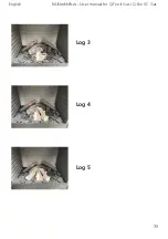
Страница 33: ...33 ceramic Logs Log 1 Log 2 Log 3 Log 4 Log 5 Log 6 Log A Log B English RAIS attika User manual for Q Tee II Gas Q Tee II C Gas ...

Страница 34: ...ot to block the holes of the center burner Position the 8 logs as shown Note the two special logs marked A and B have a groove moulded on their undersides that fits on top of the two secondary burners The glow wires are positioned between the Embers on the center burner to emphasise the glow effect Log 2 English RAIS attika User manual for Q Tee II Gas Q Tee II C Gas ...

Страница 35: ...35 Log 3 Log 4 Log 5 English RAIS attika User manual for Q Tee II Gas Q Tee II C Gas ...

Страница 36: ...36 Sample photos Log 6 Log A Log B English RAIS attika User manual for Q Tee II Gas Q Tee II C Gas ...

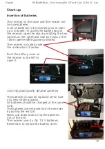
Страница 37: ...emember to replace the battery cover Start up Insertion of Batteries The receiver on the stove and the remote con trol use batteries A set of batteries to be inserted prior to start up is included To access the battery box on the receiver open the door by rotating the two catches at the right hand side by means of the 10mm open ended spanner provided The receiver is located under the combustion ch...

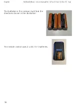
Страница 38: ...38 The batteries in the receiver must face the directions shown in the illustration The remote control uses 2 x AA 1 5 V batteries English RAIS attika User manual for Q Tee II Gas Q Tee II C Gas ...

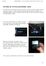
Страница 39: ... in the following manner Press and hold down the Reset button until you hear a short beep followed by a long beep Release the button Now you have 20 seconds to press the Down Arrow button on the remote control Hold down the button until you hear two short beeps from the receiver Now you can see the word conn on the remote control The receiver and remote control are now synchronised English RAIS at...

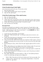
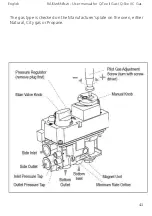
Страница 40: ... Inlet pressure tap on the gas valve and connect a ma nometer 3 Check that the pressure measured concurs with the prescribed pres sure from the gas supply company 4 Carry out the test when the stove is at maximum heat output includ ing the secondary burners and when the stove only has the pilot light ignited 5 If the pressure is low check that the gas supply pipes are the correct size 6 If the inl...

Страница 41: ...41 English RAIS attika User manual for Q Tee II Gas Q Tee II C Gas The gas type is checked on the Manufacturer s plate on the oven either Natural City gas or Propane ...

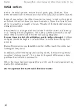
Страница 42: ...because the paintwork and ma terial need to harden but the smell will quickly disappear Ensure there is a lot of ventilation preferably a draught Children and pets should be kept at a safe distance from the stove during this process During this process you should be careful not to touch the visible sur faces glass very hot In addition while heating up and cooling down the stove may emit a so calle...

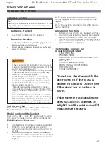
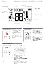
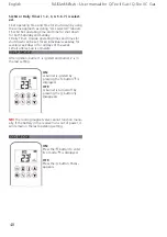
Страница 43: ... the handset Press on the and buttons at the same time Now the model number of the handset is dis played NOTE When you press on a deactivated button nothing happens and two horizontal lines are dis played NOTE Deactivation remains in effect after replace ment of batteries Activation of functions 1 Install batteries All icons are displayed and flash 2 A function is activated by pressing the relevan...

Страница 44: ...nfirmed by pressing the and buttons at the same time or waiting Change between C and F by pressing and holding the and buttons at the same time NOTE When F is selected a twelve hour clock is dis played When C is selected a twenty four hour clock is displayed ON Activation takes place by pressing the and buttons at the same time When is displayed the handset cannot be used apart from the OFF functi...

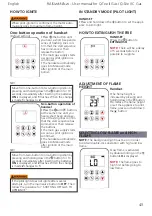
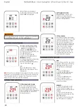
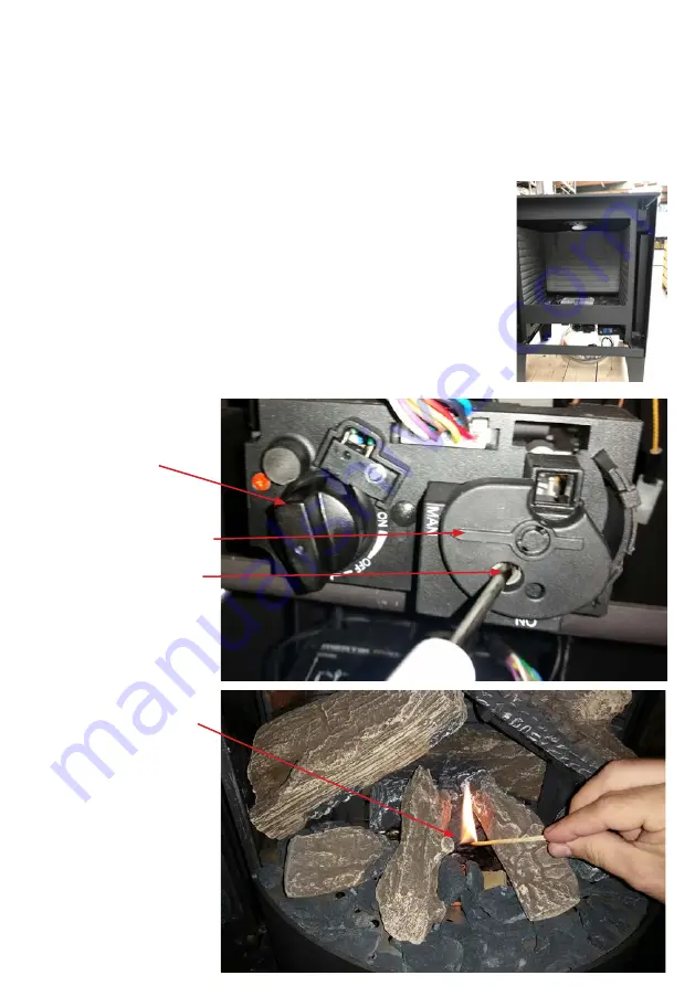
Страница 45: ...flashing lines confirm that the start sequence has commenced Then release the buttons The main gas supply starts as soon as pilot ignition is confirmed The handset automatically goes into Manual mode after ignition of the main burner NB Move from two button to one button ignition by pressing and holding down the button for 10 seconds immediately after inserting the batteries ON is displayed and 2 ...

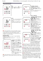
Страница 46: ...s then adjusted automatically to reach the temperature set Program mode PROGRAMS 1 and 2 can both be programmed to start or stop at specific times at a set temperature Eco mode The flame height fluctuates between high and low If the room temperature is lower than the temperature set the flame height remains at high for a longer period of time If the room temper ature is higher than the temperature...

Страница 47: ...ct hour by pressing on the or button 14 This is confirmed by pressing on the button 1 OFF is displayed ALL is displayed briefly and Min utes flashes 15 Select minutes by press ing on the or button 16 This is confirmed by pressing on the button NB Either continue to PROGRAM 2 and set oper ating time and time for shutting down or stop pro gramming here PROGRAM 2 remains deactivated NB PROGRAMS 1 and...

Страница 48: ...l days of the week Wait until set up is complete HELP MODE After ignition burner 1 is ignited and burner 2 is in the last setting ON A burner is ignited by pressing the button is displayed OFF A burner is turned off by pressing the button disappears NB The locking magnet valve cannot function manu ally If the battery in the receiver runs out of power it will remain in the last operating setting EC...

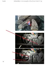
Страница 49: ...49 English RAIS attika User manual for Q Tee II Gas Q Tee II C Gas ...

Страница 50: ...50 English RAIS attika User manual for Q Tee II Gas Q Tee II C Gas ...

Страница 51: ...d 7 Put on the gas supply and check for leaks Check that the burners and pilot unit are in good condition and work 8 Refit the perforated plate 9 Refit embers and ceramic logs 10 Check the flue gas system and chimney terminal and ensure it is not blocked 11 Turn on the stove and check the set pressure 12 Ensure the stove is safe to use 13 Check that the door and other seals are in good condition a...

Страница 52: ...m cleaner Only replace damaged parts with original Rais specified parts Pack scrap ceramics in plastic bags and deliver to the correct waste locations It is recommended using a vacuum cleaner with a HEPA filter system Replace embers and close the door Ensure the stove works correctly and is safe to use Servicing of the Burners See section Conversion to bottled gas if necessary Remove the ceramic l...

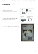
Страница 53: ...506 Mains Adapter Connecting the stove to a network 3713507 MyFire Wi Fi Box incl cable App based control of the stove 3713595 Propane Gas LP Conversion kit English RAIS attika User manual for Q Tee II Gas Q Tee II C Gas ...

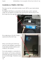
Страница 54: ...g on the Wi Fi lead into the opening marked SI The wide plug on the Wi Fi lead is inserted into the Wi Fi box When connecting the Wi Fi box use the mains adapter connection to electricity mains which is con nected to the receiver The mains adapter is connected to the receiver on the stove batteries should be removed from the receiv er to avoid leakage of batteries over time English RAIS attika Use...

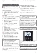
Страница 55: ...That a home network is available That the name and access code of the home network are correct That the Wi Fi router s SSID key is not hidden That the home network s signal is within range That the Wi Fi router supports the UDP protocol User Datagram Protocol CONFIRM THE SETTINGS FOR THE FIREPLACE 1 After confirming the settings for fireplace touch the Finish button A LIST OF CONNECTED MYFIRE WI F...

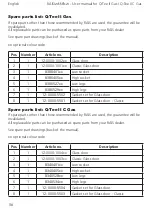
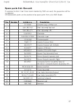
Страница 56: ...set for Glass door 8 1 12 0000 5501 Gasket set for Glass door Classic English RAIS attika User manual for Q Tee II Gas Q Tee II C Gas Spare parts list Q Tee II C Gas If spare parts other than those recommended by RAIS are used the guarantee will be invalidated All replaceable parts can be purchased as spare parts from your RAIS dealer See spare part drawings back of the manual xx optional colour c...

Страница 57: ...t 11 RA10092 Burner Top Assembly Front 12 RA10L76 Burner Raised Assembly Left 13 RA10R76 Burner Raised Assembly Right 14 RK10P07 Complete Burner Assembly Natural RK10N07 Complete Burner Assembly LPG 15 RK10 SEAL 05 Burner Seal Set 16 3711213 Grate Assembly 17 RK10_N1_GV60 Gas Valve Assembly Natural 18 RK10_P1_GV60 Gas Valve Assembly LPG 19 GV S60C 12 Latching Solenoid 20 G6R R4AS Receiver unit 21 ...

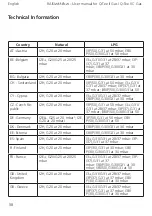
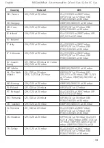
Страница 58: ...at 50 DE Germany I2ELL G25 at 20 mbar I2E G20 at 20 mbarI 3P 50 G31 at 50 mbar I3B P 50 G30 G31 at 50 DK Denmark I2H G20 at 20 mbar I3B P 30 G30 G31 at 30 mbar EE Estonia I2H G20 at 20 mbar I3B P 30 G30 G31 at 30 mbar ES Spain I2H G20 at 20 mbar I3 G31 G31 at 28 37 mbar I3P 37 G31 at 37 mbar FI Finland I2H G20 at 20 mbar I3P 30 G31 at 30 mbar I3B P 30 G30 G31 at 30 mbar FR France I2E G20 G25 at 20...

Страница 59: ...T Malta I3B P 30 G30 G31 at 30 mbar NL The Neth erlands I2L G25 at 25 mbar I2EK G25 3 at 25 mbar I3P 50 G31 at 50 mbar I3P 30 G31 at 30 mbar I3P 37 G31 at 37 mbar I3B P 30 G30 G31 at 30 mbar NO Norway I2H G20 at 20 mbar I3B P 30 G30 G31 at 30 mbar PL Poland I2E G20 at 20 mbar I3P 37 G31 at 37 mbar PT Portugal I2H G20 at 20 mbar I3 G31 G31 at 28 37 mbar I3P 37 G31 at 37 mbar RO Romania I2E G20 at 2...

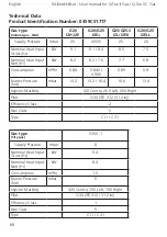
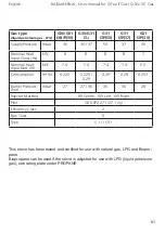
Страница 60: ...0 8 Burner Pressure hot mbar 13 2 13 2 16 4 16 6 13 4 Injector Marking 120 Centre 260 Left 260 Right Pilot G30 ZP2 312 31 2 inj Efficiency Class 2 Nox Class 5 Type C11 C31 English RAIS attika User manual for Q Tee II Gas Q Tee II C Gas Gas type City gas G150 1 Supply Pressure mbar 8 Nominal Heat Input Gross Hs kW 9 4 Nominal Heat Input Nett Hi kW 8 4 Consumption m hr 1 5 Burner Pressure hot mbar 6...

Страница 61: ...eat Input Nett Hi kW 7 4 7 4 7 4 7 4 6 5 Consumption m hr 0 225 0 225 0 29 0 29 0 29 0 253 Burner Pressure hot mbar 27 27 36 36 36 28 Injector Marking 80 Centre 100 Left 100 Right Pilot G30 ZP2 271 27 1 inj Efficiency Class 2 Nox Class 5 Type C11 C31 This stove has been tested and certified for use with natural gas LPG and Biopro pane Biopropane can be used if the stove is adjusted for use with LP...

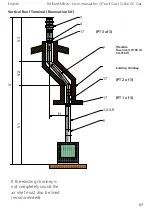
Страница 62: ...62 V 20 0 5m 20 0 5m EXAMPLES OF CHIMNEY SOLUTIONS Vertical Roof Terminal Distance V 500mm 12m min Max English RAIS attika User manual for Q Tee II Gas Q Tee II C Gas ...

Страница 63: ...a User manual for Q Tee II Gas Q Tee II C Gas Vertical Roof Terminal Renovation kit If the existing chimney is not completely sound the air inlet must also be lined recommended PT 3 of 3 PT 1 of 3 PT 2 of 3 Existing chimney Flexible flue insert Ø100 AI SA 316Ti ...

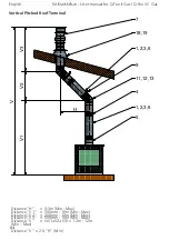
Страница 64: ...cal Pitched Roof Terminal Distance H 0 3m Min Max Distance V1 500mm 10m Min Max Distance V2 200mm 10m Min Max Distance V3 500mm 10m Min Max Distance V V1 V2 V3 1 2m 12m Min Max Distance V 2 X H Min English RAIS attika User manual for Q Tee II Gas Q Tee II C Gas ...

Страница 65: ...AIS attika User manual for Q Tee II Gas Q Tee II C Gas Vertical Roof Terminal with Bend Distance H 0 3m Min Max Distance V1 500mm 10m Min Max Distance V2 500mm 10m Min Max Distance V V1 V2 1m 12m Min Max Distance V 2 X H Min ...

Страница 66: ...sting chimney Flexible flue insert Ø100 AISA 316Ti Distance V 1m 12m Min Max Existing chimney Flue must be inspected by a qualified technician If the existing chimney is not complete ly sound the air inlet must also be lined recommended English RAIS attika User manual for Q Tee II Gas Q Tee II C Gas ...

Страница 67: ...AISA 316Ti PT 3 of 3 PT 1 of 3 PT 2 of 3 Distance H 0 3m Min Max Distance V1 500mm 10m Min Max Distance V2 200mm 10m Min Max Distance V3 500mm 10 m Min Max Distance V V1 V2 V3 1 2m 12m Min Max Distance V 2 X H Min Existing chimney with Bend Renovations kit If the existing chim ney is not completely sound the air inlet must also be lined recommended ...

Страница 68: ...68 Vertical Roof Terminal with Back outlet for more information see paragraph Location of chimney terminals English RAIS attika User manual for Q Tee II Gas Q Tee II C Gas ...

Страница 69: ...69 English RAIS attika User manual for Q Tee II Gas Q Tee II C Gas Horizontal wall Terminal for more information see paragraph Location of chimney terminals ...

Страница 70: ...70 Snorkel Snorkel Top outlet Back outlet Horizontal wall Terminal for more information see paragraph Location of chimney terminals English RAIS attika User manual for Q Tee II Gas Q Tee II C Gas ...

Страница 71: ...ee II C Gas Chimney components 1 US 25 100 Ø100 US 25 130 Ø130 Length 250mm 2 US 50 100 Ø100 US 50 130 Ø130 Length 500mm 3 US 100 100 Ø100 US 100 130 Ø130 Length 1000mm 4 USKB 100 Ø100 USKB 130 Ø130 Locking band 5 USAB 100 Ø100 USAB 130 Ø130 Protective band ...

Страница 72: ...h 7 USDV2 100 Ø100 Vertical Terminal USKB 8 USDHCE 10 Horizontal Terminal Eccentric outlet 9 USEB 100 Ø100 USEB 130 Ø130 Fitting strap 10 USMB 100 Ø100 USMB 130 Ø130 Adjustable Wall Strap English RAIS attika User manual for Q Tee II Gas Q Tee II C Gas ...

Страница 73: ...00 Ø100 USB 90 130 Ø130 90 elbow bend 14 USSR 100 Ø100 USSR 130 Ø130 Cover 12 USB 45 100 Ø100 USB 45 130 Ø130 45 elbow bend 15 USDPAL 100 Ø100 USDPAL 130 Ø130 Flat roof Cover Aluminium 13 USB 15 100 Ø100 USB 15 130 Ø130 15 elbow bend 16 USDP 100 Ø100 USDP 130 Ø130 Flat roof Cover ...

Страница 74: ...18 USDH 100 Ø100 USDH 130 Ø130 Angular Cover 5 30 21 USMPG 100 Ø100 USMPG 130 Ø130 Wall Cover 19 USLS 100 Ø100 USLS 130 Ø130 Angular Cover 20 45 22 ADAPTOR UNIVERSAL SYSTEM ADAPTOR USA Ø 100 130 USA D 99 129 English RAIS attika User manual for Q Tee II Gas Q Tee II C Gas ...

Страница 75: ...y Reaction to fire A1 Q Tee II Gas Q Tee II C Gas Distance to combustible materials Rear 75 Minimum distances mm Sides 400 For other installation settings Ceiling 450 see instruction manual Front 850 Floor 270 Risk of burning fuel falling out N D CO emission of combustion products 31 ppm G20 20 full All NOx emission 23 ppm G20 20 full All Surface temperature Pass Electrical safety Pass Cleanabilit...

Страница 76: ...76 Français ...

Страница 77: ...A A A 598 590 I E 250 D 50 149 M 76 460 410 582 291 291 149 Q Tee II Gas ...

Страница 78: ...3 1 2 0 5 400 TILLADTE AFVIGELSER FOR VINKELMÅL 50 120 120 400 0 10 0 8 400 1000 0 5 120 400 0 20 0 30 0 3 10 50 30 120 0 9 0 6 3 6 TILLADTE AFVIGELSER FOR LINIEÆRE MÅL AFVIGELSE I MM 0 1 0 1 VINKELAFVIGELSE KORTESTE SIDE 0 5 3 pr 100 mm 883 280 361 745 Established Designer Project manager Format Approved Change order Drawing change Improvement proposal Corrections D M Y ksj KSJ 361 745 ...

Страница 79: ...LADTE AFVIGELSER FOR VINKELMÅL 50 120 120 400 0 10 0 8 400 1000 0 5 120 400 0 20 0 30 0 3 10 50 30 120 0 9 0 6 3 6 TILLADTE AFVIGELSER FOR LINIEÆRE MÅL AFVIGELSE I MM 0 1 0 1 VINKELAFVIGELSE KORTESTE SIDE 0 5 3 pr 100 mm 380 983 461 845 Established Designer Project manager Format Approved Change order Drawing change Improvement proposal Corrections D M Y ksj 05 03 2018 A3 461 845 ...

Страница 80: ...3 1 2 0 5 400 TILLADTE AFVIGELSER FOR VINKELMÅL 50 120 120 400 0 10 0 8 400 1000 0 5 120 400 0 20 0 30 0 3 10 50 30 120 0 9 0 6 3 6 TILLADTE AFVIGELSER FOR LINIEÆRE MÅL AFVIGELSE I MM 0 1 0 1 VINKELAFVIGELSE KORTESTE SIDE 0 5 3 pr 100 mm 120 721 199 583 Designer Project manager Approved Change order Corrections D M Y ksj KSJ 199 583 ...

Страница 81: ... 1 2 0 5 400 TILLADTE AFVIGELSER FOR VINKELMÅL 50 120 120 400 0 10 0 8 400 1000 0 5 120 400 0 20 0 30 0 3 10 50 30 120 0 9 0 6 3 6 TILLADTE AFVIGELSER FOR LINIEÆRE MÅL AFVIGELSE I MM 0 1 0 1 VINKELAFVIGELSE KORTESTE SIDE 0 5 3 pr 100 mm 160 761 239 623 Established Designer Project manager Format Approved Change order Drawing change Improvement proposal Corrections D M Y ksj KSJ 239 623 ...

Страница 82: ...82 ...

Страница 83: ...83 A A A E 250 D 50 330 179 660 479 598 590 76 460 179 M 330 Q Tee II C Gas ...

Страница 84: ...0 5 400 TILLADTE AFVIGELSER FOR VINKELMÅL 50 120 120 400 0 10 0 8 400 1000 0 5 120 400 0 20 0 30 0 3 10 50 30 120 0 9 0 6 3 6 TILLADTE AFVIGELSER FOR LINIEÆRE MÅL AFVIGELSE I MM 0 1 0 1 VINKELAFVIGELSE KORTESTE SIDE 0 5 3 pr 100 mm 0 361 745 0 280 883 Q Tee II C Gas Low Socket Bend Tool Established Designer Project manager Format Approved Change order Drawing change Improvement proposal Correction...

Страница 85: ...FOR VINKELMÅL 50 120 120 400 0 10 0 8 400 1000 0 5 120 400 0 20 0 30 0 3 10 50 30 120 0 9 0 6 3 6 TILLADTE AFVIGELSER FOR LINIEÆRE MÅL AFVIGELSE I MM 0 1 0 1 VINKELAFVIGELSE KORTESTE SIDE 0 5 3 pr 100 mm 0 380 983 0 461 845 Remarks Bend Tool Established Designer Project manager Format Approved INDUSTRIVEJ 20 9900 FREDERIKSHAVN DENMARK Change order Drawing change Improvement proposal Corrections D ...

Страница 86: ...00 0 20 0 30 0 3 10 50 30 120 0 9 0 6 3 6 TILLADTE AFVIGELSER FOR LINIEÆRE MÅL AFVIGELSE I MM 0 1 0 1 VINKELAFVIGELSE KORTESTE SIDE 0 5 3 pr 100 mm 0 120 723 0 201 585 Material Remarks Bend Tool Established Designer Project manager Format Approved INDUSTRIVEJ 20 9900 FREDERIKSHAVN DENMARK Phone 45 98 47 90 33 Fax 45 98 47 92 91 E mail info rais dk Homepage www rais dk Change order Drawing change I...

Страница 87: ...0 400 0 10 0 8 400 1000 0 5 120 400 0 20 0 30 0 3 10 50 30 120 0 9 0 6 3 6 TILLADTE AFVIGELSER FOR LINIEÆRE MÅL AFVIGELSE I MM 0 1 0 1 VINKELAFVIGELSE KORTESTE SIDE 0 5 3 pr 100 mm 0 165 768 0 246 630 Remarks Bend Tool Established Designer Project manager Format Approved INDUSTRIVEJ 20 9900 FREDERIKSHAVN DENMARK Phone 45 98 47 90 33 Fax 45 98 47 92 91 Change order Drawing change Improvement propos...

Страница 88: ...VIGELSER FOR VINKELMÅL 50 120 120 400 0 10 0 8 400 1000 0 5 120 400 0 20 0 30 0 3 10 50 30 120 0 9 0 6 3 6 TILLADTE AFVIGELSER FOR LINIEÆRE MÅL AFVIGELSE I MM 0 1 0 1 VINKELAFVIGELSE KORTESTE SIDE 0 5 3 pr 100 mm 1 2 3 4 5 6 7 8 Q Tee II Gas Spareparts ...

Страница 89: ...ER FOR VINKELMÅL 50 120 120 40 0 10 0 8 400 100 0 5 120 400 0 20 0 30 0 3 10 50 30 120 0 9 0 6 3 6 TILLADTE AFVIGELSER FOR LINIEÆRE MÅL AFVIGELSE I MM 0 1 0 1 VINKELAFVIGELSE KORTESTE SIDE 0 5 3 pr 100 mm 1 2 3 4 5 6 8 7 Q Tee II C Gas Spareparts ...

Страница 90: ...RAIS A S Industrivej 20 DK 9900 Frederikshavn Denmark www rais dk ATTIKA FEUER AG Brunnmatt 16 CH 6330 Cham Switzerland www attika ch ...

Страница 91: ......
Отзывы: