


ESP-SMTe Controller
6
Station Numbering
Fixed Station Numbering Description
The controller is configured with Fixed Station Numbering.
Each bay is set up to accept a 6 station module and reserve
the station number for future use if a 6 station module is
NOT installed in Bays 2, 3 or 4.
Station numbers are pre-assigned as follows:
VT MV COM
VT MV COM
5
6
7
11
12
13
17
18
19
1
2
3
4
8
9
10
14
15
16
20
21
22
Bay 1
Bay 2
Bay 3
Bay 4
Example Of Recommended Installation For 19 Stations
Module Configuration
Example of installation with station numbering gaps:
• A total of 19 stations are installed.
• The Base Module is installed in Bay 1 and uses Stations
1 through 4.
• A 6-Station Expansion Module is installed in Bays 2 and
3 using Stations 5 through 16.
• A 3-Station module is installed in Bay 4 and uses sta-
tions numbered 17 through 19.
Because a 3-Station module is installed in Bay 4, only the
first three station numbers assigned to that bay will be used
and the unused numbers will be “reserved” for future use.
During programming, the controller will skip any unused
station numbers, creating a gap in station numbering.
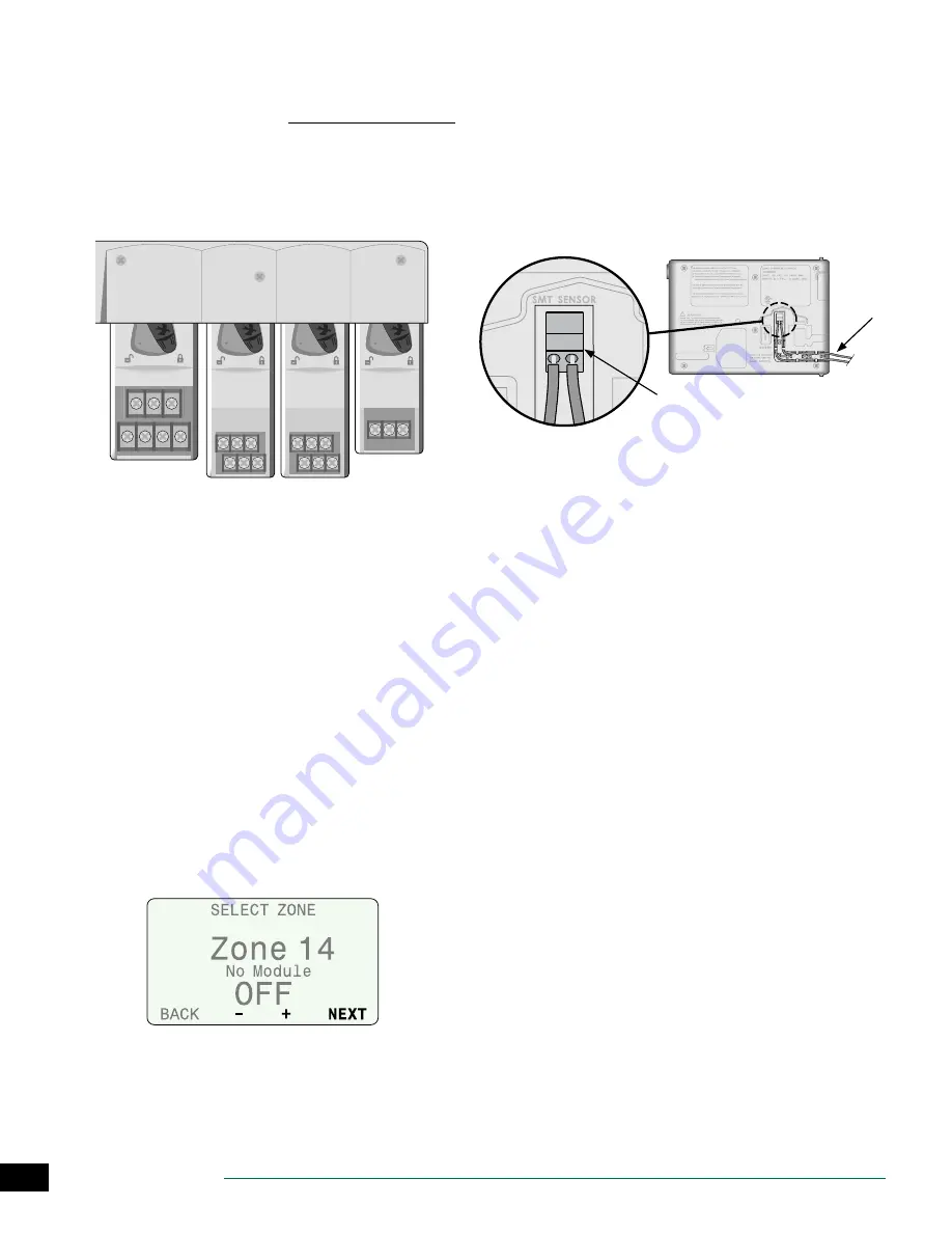
For the previous example, the first screen of the Zone Setup
Wizard is displayed. The “No Module” message indicates
there is no module associated with Zone 14.
c
b
NOTE: Station numbering gaps will not prevent the
controller from operating properly. It only affects
station numbering. During programming when
connected to AC power, the controller will skip any
unused stations where a module is not installed.
Connect Weather Sensor Wire to
Controller
A
Begin by running 18-2 AWG, UV rated wire from sensor
to controller (200 ft. max.)
c
b
NOTE: 25 feet of 18-2 AWG, UV rated wire is provided.
B
Strip wire insulation approx 3/8” and insert leads into
connector located on back of front panel (polarity not
important).
B
C
C
Route the two wires through the provided channel
and out through one of the knockouts, located in the
bottom of the controller cabinet.
Complete Controller Installation
A
Reinstall and reconnect the front panel.
B
Apply power to the controller and test the system.
c
b
NOTE: The electrical connections can be checked
even if water is not available. If water is available and
you would like to test some or all of your stations, use
the Test All Stations feature of the controller.Weather
Sensor Installation