


Rear Panel Interfaces
DMDVB20 LBST Satellite Modem
5-2
TM138 – Rev. 1.0
5.2 Power Input Modules
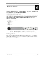
5.2.1 AC Power Input Module
AC Input Module (Figure 5-1) is located on the left side of the unit. Power applied to the port with
the supplied power cable is 100 – 240 VAC, 50 – 60 Hz. Integrated into the Power Input Module
is the Power On/Off Rocker Switch. Power consumption for the unit is 1A. A chassis ground
connection (#10-32 threaded stud), is located to the lower right of the module .5.2.2 DC Power
Input/Switch
The Optional DC Power Input and Switch (Figure 5-1) is available for all DMDVB20 LBST
products. The unit may be powered from a 36 – 75 VDC source with a maximum unit power
consumption of 3 A. Refer to Table 5-1 for pinouts.
Table 5-1. DC Power
A –
B Ground
C +
5.3 DMDVB20 LBST Chassis Connections
5.3.1 EXT REF (J10)
The External Reference Port is a 50-Ohm Female BNC Connector and will accept the following
frequencies: 1.0, 1.544, 2.0, 2.048, 5.0, and 10.0 MHz.
5.3.2 TX L-Band IF (J11)
The Transmit Output Port is a 50-Ohm Type-N Connector. The power level is programmable
from 0 to -25 dBm, in 0.1 dBm steps. The IF Frequency can be programmed to 950 – 2050 MHz,
in 1 Hz Steps.
5.3.3 RX (J1)
The Receive Input Port is a 75-Ohm F-Type Connector. The IF Frequency can be programmed
from 950 to 2150 MHz in 1 Hz Steps.
5.3.4 ALARM (J15)
The Alarm Port is a 15-Pin Female “D” Connector. Refer to Table 5-2 for pinouts.
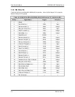
Table 5-2. ALARM Port 15-Pin Female “D” Connector (J15)
Pin No.
Signal Name
Signal
Direction
1
Mod Fault
MF-C
No Direction
2
Mod Fault
MF-NC
No Direction
3
Mod Fault
MF-NO
No Direction
4
Demod Fault
DF-C
No Direction
Содержание DMDVB20 LBST
Страница 11: ...Table of Contents DMDVB20 LBST Satellite Modem xii TM138 Rev 1 0...
Страница 14: ...DMDVB20 LBST Satellite Modem Introduction TM138 Rev 1 0 1 3...
Страница 20: ...Installation DMDVB20 LBST Satellite Modem 2 6 TM138 Rev 1 0...
Страница 29: ...DMDVB20 LBST Satellite Modem Theory of Operation TM138 Rev 1 0 3 9 Figure 3 5 Loopback Functional Block Diagram...
Страница 36: ...Theory of Operation DMDVB20 LBST Satellite Modem 3 16 TM138 Rev 1 0...
Страница 67: ...DMDVB20 LBST Satellite Modem User Interfaces TM138 Rev 1 0 4 31...
Страница 73: ...Rear Panel Interfaces DMDVB20 LBST Satellite Modem 5 6 TM138 Rev 1 0...
Страница 79: ...Maintenance and Troubleshooting DMDVB20 LBST Satellite Modem 6 6 TM138 Rev 1 0...
Страница 88: ...DMDVB20 LBST Satellite Modem Technical Specifications TM138 Rev 1 0 7 9...
Страница 90: ...Appendix A DMDVB20 LBST Satellite Modem A 2 TM138 Rev 1 0...
Страница 97: ...DMDVB20 LBST Satellite Modem Appendix B TM138 Rev 1 0 B 7...
Страница 100: ...DMDVB20 LBST Satellite Modem Appendix C TM138 Rev 1 0 C 3...
Страница 107: ...DMDVB20 LBST Satellite Modem Appendix D TM138 Rev 1 0 D 7...