


DMDVB20 LBST Satellite Modem
User Interfaces
TM138 – Rev. 1.0
4-29
4.4 Terminal Mode Control
The Terminal Mode Control allows the use of an external terminal or computer to monitor and
control the modem from a full screen interactive presentation operated by the modem itself. No
external software is required other than VT-100 Terminal Emulation Software (e.g. “Procomm”
for a computer when used as a terminal. The Control Port is normally used as an RS–232
Connection to the terminal device. The RS-232 operating parameters can be set using the
modem Front Panel and stored in EEPROM for future use.
Refer to the DMDVB20 LBST Remote Protocol Manual (TM137) for the
terminal screens.
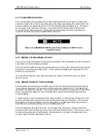
4.4.1 Modem Terminal Mode Control
The modem can be interactively monitored and controlled in the Terminal Mode, with a full screen
presentation of current settings and status.
The Terminal Control Mode supports several baud rates, however the connection must be set for
8 data bits, 1 stop bit and no parity (8,N,1). Three terminal emulations are supported: VT-100,
WYSE 50, and ADDS-VP.
“$” is used for setting the screen when the terminal is used for the first time the non-volatile
memory is reset.
4.4.2 Modem Setup for Terminal Mode
Terminal Mode Communications and Protocol is set from the Front Panel Control by setting the
“Control Mode” Parameter to “Terminal”, and then setting the “Modem Port”, “Term Baud” and
“Emulation” Parameters as desired. Then a terminal is connected to Connector J20 on the Back
Panel. All operating software for the Terminal Mode is contained within the Modem Internal
Control Software.
A “break” signal on the communications line, pressing “ESC” on the terminal or Power On of the
modem will initiate full screen terminal mode printing and redraw the full screen. The Terminal
Mode displays the present status of all user parameters controlled and read by the processor,
and offers a menu allowing change to any controlled parameter.
The Terminal Mode uses eight “Screens,” each of which have the basic contents of the three
modem monitor and control areas as set in the Front Panel matrix columns. This screen is used
for setting the parameters of the Modulator, Demodulator, Event, Alarm, Latched Alarm, Drop
Controls, Insert Controls, and Interface Areas.
Содержание DMDVB20 LBST
Страница 11: ...Table of Contents DMDVB20 LBST Satellite Modem xii TM138 Rev 1 0...
Страница 14: ...DMDVB20 LBST Satellite Modem Introduction TM138 Rev 1 0 1 3...
Страница 20: ...Installation DMDVB20 LBST Satellite Modem 2 6 TM138 Rev 1 0...
Страница 29: ...DMDVB20 LBST Satellite Modem Theory of Operation TM138 Rev 1 0 3 9 Figure 3 5 Loopback Functional Block Diagram...
Страница 36: ...Theory of Operation DMDVB20 LBST Satellite Modem 3 16 TM138 Rev 1 0...
Страница 67: ...DMDVB20 LBST Satellite Modem User Interfaces TM138 Rev 1 0 4 31...
Страница 73: ...Rear Panel Interfaces DMDVB20 LBST Satellite Modem 5 6 TM138 Rev 1 0...
Страница 79: ...Maintenance and Troubleshooting DMDVB20 LBST Satellite Modem 6 6 TM138 Rev 1 0...
Страница 88: ...DMDVB20 LBST Satellite Modem Technical Specifications TM138 Rev 1 0 7 9...
Страница 90: ...Appendix A DMDVB20 LBST Satellite Modem A 2 TM138 Rev 1 0...
Страница 97: ...DMDVB20 LBST Satellite Modem Appendix B TM138 Rev 1 0 B 7...
Страница 100: ...DMDVB20 LBST Satellite Modem Appendix C TM138 Rev 1 0 C 3...
Страница 107: ...DMDVB20 LBST Satellite Modem Appendix D TM138 Rev 1 0 D 7...