


User Interfaces
DMDVB20 LBST Satellite Modem
4-12
TM138 – Rev. 1.0
GOLD SEQ N
{000000}
Allows the user to enter specific tap value to choose
different gold sequences for the S2 scrambler. The unit
are decimal and the maximum value allow is 2
18
-1.
ODU-LNB (menu)
LO FREQ (MHz)
Allows the user to enter the LNB Local Oscillator
frequency in MHz in order for the downlink frequency to
be displayed correctly (refer to the LNB manufacturer’s
specifications).
OSC SIDE BAND
{LOW SIDEBAND, HIGH SIDEBAND}
Allows the user to select the location of the LNB LO.
The user must enter the location of the LNB LO in order
for the DOWNLINK FREQUENCY to be displayed
correctly. The LNB LO can be either higher or lower in
frequency than the LNB output frequency. If the LNB LO
is higher in frequency then the user must enter HIGH
SIDEBAND.
10 MHz LNB REF
{ENABLED, DISABLED}
Allows the user to enable or disable the 10 MHz BUC
reference clock.
VOLTAGE SELECT
{13, 15, 18, 20}
Allows the user to select the voltage required by the LNB
(refer
to
the
LNB
manufacturer’s
specifications)
LNB VOLTAGE
{ENABLED, DISABLED}
Allows the user to enable or disable the LNB supply
voltage.
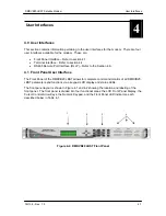
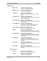
4.3.4 Interface Menu Options and Parameters
TX SETUP (menu)
CIRCUIT ID
Allows the user entry of a Tx Circuit Identifier. Circuits
can be given up to an 11 Character alphanumeric
identity such as LINK1.
TERR INTERFACE
STANDARD INTERFACE
{RS422
SERIAL,RS232 SERIAL, V.35}
Allows the user to select the Transmit Interface Type.
TX CLK SRC
{SCTE, SCT, EXT CLK}
Allows the user to select the Transmit Clock Source.
TX CLK POL
{AUTO, NORMAL, INVERTED}
Allows the user to select the Clock Polarity for the Tx
Terrestrial Clock relative to the Tx Data. “Auto” detects
wrong polarity and automatically corrects. If G.703
Interface is selected, this selection cannot be changed.
Содержание DMDVB20 LBST
Страница 11: ...Table of Contents DMDVB20 LBST Satellite Modem xii TM138 Rev 1 0...
Страница 14: ...DMDVB20 LBST Satellite Modem Introduction TM138 Rev 1 0 1 3...
Страница 20: ...Installation DMDVB20 LBST Satellite Modem 2 6 TM138 Rev 1 0...
Страница 29: ...DMDVB20 LBST Satellite Modem Theory of Operation TM138 Rev 1 0 3 9 Figure 3 5 Loopback Functional Block Diagram...
Страница 36: ...Theory of Operation DMDVB20 LBST Satellite Modem 3 16 TM138 Rev 1 0...
Страница 67: ...DMDVB20 LBST Satellite Modem User Interfaces TM138 Rev 1 0 4 31...
Страница 73: ...Rear Panel Interfaces DMDVB20 LBST Satellite Modem 5 6 TM138 Rev 1 0...
Страница 79: ...Maintenance and Troubleshooting DMDVB20 LBST Satellite Modem 6 6 TM138 Rev 1 0...
Страница 88: ...DMDVB20 LBST Satellite Modem Technical Specifications TM138 Rev 1 0 7 9...
Страница 90: ...Appendix A DMDVB20 LBST Satellite Modem A 2 TM138 Rev 1 0...
Страница 97: ...DMDVB20 LBST Satellite Modem Appendix B TM138 Rev 1 0 B 7...
Страница 100: ...DMDVB20 LBST Satellite Modem Appendix C TM138 Rev 1 0 C 3...
Страница 107: ...DMDVB20 LBST Satellite Modem Appendix D TM138 Rev 1 0 D 7...