


User Interfaces
DMD50 Universal Satellite Modem
4-18
TM118 – Rev. 1.1
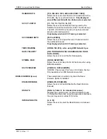
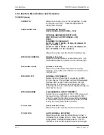
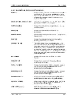
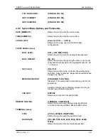
RX SETUP (menu)
CIRCUIT ID
Provides entry of Rx Circuit Identifier. Circuits can be
given up to an 11 Character alphanumeric Identity such
as DLINK1
TERR
INTERFACE
STANDARD
INTERFACE
{RS422
SERIAL,RS232 SERIAL, V.35}
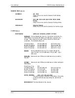
OPTIONAL
HARDWARE
INTERFACES:
{M2P PARALLEL, DVB PARALLEL, ASI}
{HSSI}
{ETHERNET 10/100 BASE-T}
{G.703: T1 AMI, T1 B8ZS, , E1 BAL, E1 UNBAL, T2
BAL, T2 UNBAL, E2}
{G.703: T1 AMI, T1 B8ZS, , E1 BAL, E1 UNBAL, T2
BAL, T2 UNBAL, E2, E3, T3, STS1}
Allows the user to select the Transmit Interface
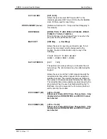
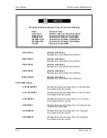
BUFF SIZE (msec)
{0 - 64 msecs}
Allows the user to set the Doppler Buffer Size in msec.
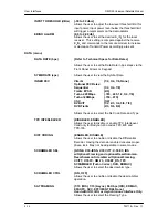
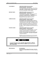
BUFFER
CLK
SRC
The user must assign priorities to the clock sources. 1
being the highest priority and 5 being the last resort.
The menu has three fields; the first field is the name of
the clock source, the second field is the priority entry
area, and the last field is the depth of the list. In the
priority field, the up/down arrow keys will scroll through
the list displaying the names and the current priority.
When the desired clock name is displayed, the number
keys may be used to assign a priority value. Pressing
<Enter> will re-sort the list. Do this until the clock
sources are prioritized in the order desired. Use the
left/right arrow keys to move the cursor to the depth field.
This field assigns the number of entries to use. The
number keypad or the up/down arrows can be used to
change the value.
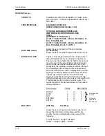
Clock Source
Priority
SRC DEPTH
RX SAT
1
of 3
SCTE
2
of
3
SCT
3
of
3
EXT BNG
4
of
3
EXT IDI
5
of
3
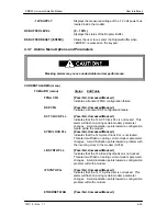
MAP COPY
{SRC Map Dest Map}
Allows the user to copy drop and insert maps. Tx Act
map is the drop map currently being used by the
modem. Source and destination may be any of the
following:
TX ACT, RX ACT, TX EDIT, RX EDIT,
USER 1 - USER 8, ROM 1 -ROM 8
Only these will
be used
Will not be
used since
4>3 and 5>3
Содержание DMD50
Страница 2: ......
Страница 3: ......
Страница 16: ...DMD50 Universal Satellite Modem Table of Contents TM118 Rev 1 1 xv...
Страница 17: ......
Страница 20: ...DMD50 Universal Satellite Modem Introduction TM118 Rev 1 1 1 3...
Страница 21: ......
Страница 27: ...Installation DMD50 Universal Satellite Modem 2 6 TM118 Rev 1 1...
Страница 53: ...Theory of Operation DMD50 Universal Satellite Modem 3 26 TM118 Rev 1 1...
Страница 97: ...User Interfaces DMD50 Universal Satellite Modem 4 44 TM118 Rev 1 1...
Страница 122: ...DMD50 Universal Satellite Modem Rear Panel Interfaces TM118 Rev 1 1 5 25...
Страница 123: ......
Страница 132: ...DMD50 Universal Satellite Modem Maintenance and Troubleshooting TM118 Rev 1 1 6 9...
Страница 133: ......
Страница 158: ...DMD50 Universal Satellite Modem Technical Specifications TM118 Rev 1 1 7 25...
Страница 159: ......
Страница 162: ...DMD50 Universal Satellite Modem Appendix A TM118 Rev 1 1 A 3...
Страница 163: ......
Страница 170: ...DMD50 Universal Satellite Modem Appendix B TM118 Rev 1 1 B 7...
Страница 171: ......
Страница 174: ...DMD50 Universal Satellite Modem Appendix C TM118 Rev 1 1 C 3...
Страница 175: ......
Страница 184: ...DMD50 Universal Satellite Modem Appendix D TM118 Rev 1 1 D 9...
Страница 185: ......
Страница 192: ...DMD50 Universal Satellite Modem Appendix E TM118 Rev 1 1 E 7...
Страница 193: ......
Страница 200: ...DMD50 Universal Satellite Modem Appendix F TM118 Rev 1 1 F 7...
Страница 201: ......
Страница 205: ...Appendix G DMD50 Universal Satellite Modem G 4 TM118 Rev 1 1...
Страница 209: ...Appendix H DMD50 Universal Satellite Modem H 4 TM118 Rev 1 1 Figure H 5 Insert Only with Internal Frame Source...
Страница 224: ...DMD50 Universal Satellite Modem Appendix H TM118 Rev 1 1 H 19...
Страница 225: ......
Страница 231: ...Appendix I DMD50 Universal Satellite Modem I 6 TM118 Rev 1 1...


