


Theory of Operation
DMD50 Universal Satellite Modem
3-24
TM118 – Rev. 1.1
Slot Bits = (6,312,000 * (7 * 10))/(22,092 * (7 + 1)) = 2,500
Actual Ratio = (2,500+ 10)/2,500= 1.004
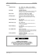
3.13.5 SCC Overhead Channel Setup
1.
Set the Framing Mode (located under Mod and Demod Data Menus) to SCC.
After doing this, two new menus will appear to the right of the Framing Menu, for
both the Mod and Demod. The new menus will be:
SCC CTL RATIO
SCC INBAND RATE
2.
Set the desired SCC control ratio:
SCC CTL RATIO {1/1, 1/2, 1/3, 1/4, 1/5, 1/6, 1/7}
This allows the user to simulate the framing used by the Satellite Control
Channel Option (Pass-Thru Mode only). The SCC CTL RATIO is the ratio of
overhead in-band data to synchronizing words.
3.
Set the desired SCC in-band rate:
SCC INBAND RATE {300 to 200000}
This allows the user to request the rate of in-band data for the overhead channel.
This sets the overhead amount only. The actual amount of data that can be
passed through the overhead channel will be set under “ES Baud Rate” (see
Step 6 below).
4.
Under the Interface > General menus, locate the TX ASYNC MODE (menu).
5.
Under the TX ASYNC MODE Menu, set the desired ES Interface type:
ES INTERFACE {RS-232, RS-485}
This allows the user to select the interface type.
6.
Under TX ASYNC MODE Menu, set the desired baud rate for the ASYNC Port
(J17). This will be the baud rate that will pass through the overhead channel:
ES BAUD RATE {150 - 19200}
This allows the user to select the baud rate of the ASYNC port (J17) in SCC
Mode.
7.
Under TX ASYNC MODE Menu, set the desired ES BITS/CHAR:
ES BITS/CHAR {7,8}
This allows the user to choose between 7 or 8 bits of data.
8.
Repeat Steps 4 through 7 under the RX ASYNC MODE (menu)
9.
The physical connection to the overhead channel will be the DB-9 Female Port
labeled ASYNC (J17).
Содержание DMD50
Страница 2: ......
Страница 3: ......
Страница 16: ...DMD50 Universal Satellite Modem Table of Contents TM118 Rev 1 1 xv...
Страница 17: ......
Страница 20: ...DMD50 Universal Satellite Modem Introduction TM118 Rev 1 1 1 3...
Страница 21: ......
Страница 27: ...Installation DMD50 Universal Satellite Modem 2 6 TM118 Rev 1 1...
Страница 53: ...Theory of Operation DMD50 Universal Satellite Modem 3 26 TM118 Rev 1 1...
Страница 97: ...User Interfaces DMD50 Universal Satellite Modem 4 44 TM118 Rev 1 1...
Страница 122: ...DMD50 Universal Satellite Modem Rear Panel Interfaces TM118 Rev 1 1 5 25...
Страница 123: ......
Страница 132: ...DMD50 Universal Satellite Modem Maintenance and Troubleshooting TM118 Rev 1 1 6 9...
Страница 133: ......
Страница 158: ...DMD50 Universal Satellite Modem Technical Specifications TM118 Rev 1 1 7 25...
Страница 159: ......
Страница 162: ...DMD50 Universal Satellite Modem Appendix A TM118 Rev 1 1 A 3...
Страница 163: ......
Страница 170: ...DMD50 Universal Satellite Modem Appendix B TM118 Rev 1 1 B 7...
Страница 171: ......
Страница 174: ...DMD50 Universal Satellite Modem Appendix C TM118 Rev 1 1 C 3...
Страница 175: ......
Страница 184: ...DMD50 Universal Satellite Modem Appendix D TM118 Rev 1 1 D 9...
Страница 185: ......
Страница 192: ...DMD50 Universal Satellite Modem Appendix E TM118 Rev 1 1 E 7...
Страница 193: ......
Страница 200: ...DMD50 Universal Satellite Modem Appendix F TM118 Rev 1 1 F 7...
Страница 201: ......
Страница 205: ...Appendix G DMD50 Universal Satellite Modem G 4 TM118 Rev 1 1...
Страница 209: ...Appendix H DMD50 Universal Satellite Modem H 4 TM118 Rev 1 1 Figure H 5 Insert Only with Internal Frame Source...
Страница 224: ...DMD50 Universal Satellite Modem Appendix H TM118 Rev 1 1 H 19...
Страница 225: ......
Страница 231: ...Appendix I DMD50 Universal Satellite Modem I 6 TM118 Rev 1 1...


