
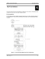


Rear Panel Interfaces
DMD50 Universal Satellite Modem
5-6
TM118 – Rev. 1.1
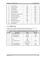
When operating the remote port as RS232 using a cable pinned 1 for 1
may cause communication failures due to miss routing of standard
RS232 com port signals.
When operating the remote port as RS232, the cable used should only
have pins 2, 3 and 5 connected.
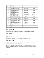
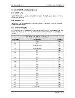
5.3.12 ETHERNET (J21)
The ETHERNET Port (J21) can be used for the Monitor & Control (M&C) Functions of the unit.
The physical interface is a standard female RJ-45 Connector.
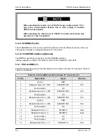
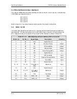
5.4 G.703 IDR/IBS Interface (Optional)
The DMD50 supports two versions of the G703 IDR/IBS interface.
Interface options are G703 T1/E1/T2/E2 or G703 T1/E1/T2/E2/E3/T3 and STS1.
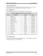
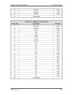
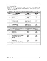
5.4.1 ESC ALARM (J1)
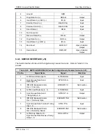
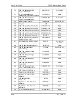
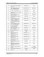
The ESC (Engineering Service Circuits) Alarms Port is a 25-Pin Female “D” Connector. Refer to
Table 5-6 for pinouts.
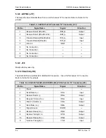
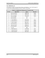
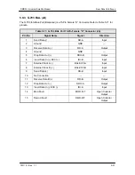
Table 5-6. ESC ALARM Port 25-Pin Female “D” Connector (J1)
Pin No.
Signal Name
Signal
Direction
1 Ground
GND ---
2
Backward Alarm Out - 1NO
ESCBWO 1NO
N/A
3 No
Connection
NC
---
4
Backward Alarm Out - 2 NO
ESCBWO 2NO
N/A
5 No
Connection
NC
---
6
Backward Alarm Out - 3 NO
ESCBWO 3NO
N/A
7 Ground
GND ---
8
Backward Alarm Out - 4 NO
ESCBWO 4NO
N/A
9 No
Connection
NC
---
10
Backward Alarm In - 2
ESCBWI 2
Input
11
Backward Alarm In - 4
ESCBWI 4
Input
12 No
Connection
NC
---
13 No
Connection
NC
---
14
Backward Alarm Out - 1 C
ESCBWO 1C
N/A
Содержание DMD50
Страница 2: ......
Страница 3: ......
Страница 16: ...DMD50 Universal Satellite Modem Table of Contents TM118 Rev 1 1 xv...
Страница 17: ......
Страница 20: ...DMD50 Universal Satellite Modem Introduction TM118 Rev 1 1 1 3...
Страница 21: ......
Страница 27: ...Installation DMD50 Universal Satellite Modem 2 6 TM118 Rev 1 1...
Страница 53: ...Theory of Operation DMD50 Universal Satellite Modem 3 26 TM118 Rev 1 1...
Страница 97: ...User Interfaces DMD50 Universal Satellite Modem 4 44 TM118 Rev 1 1...
Страница 122: ...DMD50 Universal Satellite Modem Rear Panel Interfaces TM118 Rev 1 1 5 25...
Страница 123: ......
Страница 132: ...DMD50 Universal Satellite Modem Maintenance and Troubleshooting TM118 Rev 1 1 6 9...
Страница 133: ......
Страница 158: ...DMD50 Universal Satellite Modem Technical Specifications TM118 Rev 1 1 7 25...
Страница 159: ......
Страница 162: ...DMD50 Universal Satellite Modem Appendix A TM118 Rev 1 1 A 3...
Страница 163: ......
Страница 170: ...DMD50 Universal Satellite Modem Appendix B TM118 Rev 1 1 B 7...
Страница 171: ......
Страница 174: ...DMD50 Universal Satellite Modem Appendix C TM118 Rev 1 1 C 3...
Страница 175: ......
Страница 184: ...DMD50 Universal Satellite Modem Appendix D TM118 Rev 1 1 D 9...
Страница 185: ......
Страница 192: ...DMD50 Universal Satellite Modem Appendix E TM118 Rev 1 1 E 7...
Страница 193: ......
Страница 200: ...DMD50 Universal Satellite Modem Appendix F TM118 Rev 1 1 F 7...
Страница 201: ......
Страница 205: ...Appendix G DMD50 Universal Satellite Modem G 4 TM118 Rev 1 1...
Страница 209: ...Appendix H DMD50 Universal Satellite Modem H 4 TM118 Rev 1 1 Figure H 5 Insert Only with Internal Frame Source...
Страница 224: ...DMD50 Universal Satellite Modem Appendix H TM118 Rev 1 1 H 19...
Страница 225: ......
Страница 231: ...Appendix I DMD50 Universal Satellite Modem I 6 TM118 Rev 1 1...


