


Electrical Interfaces
DMD2401/DMD2401L/DMD2401 IBS/IDR Satellite Modem
5-28
TM065 – Rev. 3.3
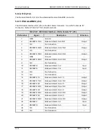
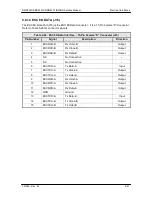
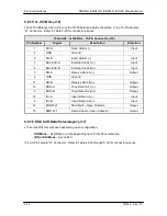
Table 5-25. Sync Data - Cable Number CA/4826 Pinouts
Pin Number
Signal
Description
Direction
4
SD-A
Send Data A (-)
Input
22
SD-B
Send Data B (+)
Input
5
ST-A
Send Timing A (-)
Output
23
ST-B
Send Timing B (+)
Output
6
RD-A
Receive Data A (-)
Output
24
RD-B
Receive Data B (+)
Output
7
RS-A
Request to Send A (-)
Input
25
RS-B
Request to Send B (+)
Input
8
RT-A
Receive Timing A (-)
Output
26
RT-B
Receive Timing B (+)
Output
9
CS-A
Clear to Send A (-)
Output
14
MF
Mod Fault - Open Collector
Output
33
DF
Demod Fault - Open Collector
Output
27
CS-B
Clear to Send B (+)
Output
11*
DM-A
Data Mode A (-)
Output
29*
DM-B
Data Mode B (+)
Output
13
RR-A
Receiver Ready A (-)
Output
31
RR-B
Receiver Ready B (+)
Output
3
BAL EXC-A
External Clock A (-)
Input
21
BAL EXC-B
External Clock B (+)
Input
16
RX-0-A
Receive Octet A (-)
Output
34
RX-0 B
Receive Octet B (+)
Output
17
TT-A
Terminal Timing A (-)
Input
35
TT-B
Terminal Timing B (+)
Input
1, 19, 20, 37
GND
Signal Ground
–
*
Note: The DMD2401 Satellite Modem constantly asserts the DM/DSR Signal (DM and DSR
are actually the same signal). The modem is always in the condition of being able to
accept data. DTR Input to the modem is not necessary and is ignored. The DM/DSR
Output of the modem is located on Pins 11 and 29 as shown above.
Содержание DMD2401 IBS
Страница 2: ......
Страница 15: ......
Страница 39: ...Operation DMD2401 DMD2401L DMD2401 IBS IDR Satellite Modem 3 16 TM065 Rev 3 3 Figure 3 9 IF Loopback...
Страница 60: ...DMD2401 DMD2401L DMD2401 IBS IDR Satellite Modem User Interfaces TM065 Rev 3 3 4 21...
Страница 199: ...Appendices DMD2401 DMD2401L DMD2401 IBS IDR Satellite Modem 8 12 TM065 Rev 3 3 This Page is Intentionally Left Blank...