


Electrical Interfaces
DMD2401/DMD2401L/DMD2401 IBS/IDR Satellite Modem
5-24
TM065 – Rev. 3.3
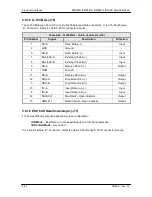
5.7.5 TERMINAL (J5)
The Terminal Port (J5) pinouts are listed below in Table 5-20.
Table 5-20. RS-232 Terminal Port – 9-Pin Female “D” Connector (J5)
Pin Number
Signal
Description
Direction
2
TxD
Transmit Data
Input
3
RxD
Receive Data
Output
5
GND
Ground
–
5.7.6 ALARM (J6)
The modem has two Form-C Dry Contact Alarm Relays onboard and an Alarm Connector located
on the rear panel, the 9-pin male “D” sub connector (J6).
The two relays are designated Modulator Alarm and Demodulator Alarm. Non-Alarm is defined as
the powered state of the relay. Thus, if there is a Modulator Alarm and/or Demodulator Alarm, the
pins will be connected as shown in Table 5-21:
Table 5-21. Alarm Relays
Alarm
No Alarm
Modulator
Pins 2 and 3 Shorted
Pins 1 and 2 Shorted
Demodulator
Pins 8 and 9 Shorted
Pin 7 and 8 Shorted
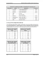
The pin definitions for J6 are shown in Table 5-22 below.
Note: The NC and NO (Normally Closed and Normally Open) nomenclature applies to non-
energized relays.
Table 5-22. Alarm Connector Pin Assignment (J6)
J6 Pin
Number
Connection
1
Mod Alarm Relay A NO on Alarm
2
Mod Alarm Relay A Common
3
Mod Alarm Relay A NC on Alarm
4
5
AGC Voltage Output
6
GND
7
Demod Alarm Relay B NO on Alarm
8
Demod Alarm Relay B Common
9
Demod Alarm Relay B NC on Alarm
Содержание DMD2401 IBS
Страница 2: ......
Страница 15: ......
Страница 39: ...Operation DMD2401 DMD2401L DMD2401 IBS IDR Satellite Modem 3 16 TM065 Rev 3 3 Figure 3 9 IF Loopback...
Страница 60: ...DMD2401 DMD2401L DMD2401 IBS IDR Satellite Modem User Interfaces TM065 Rev 3 3 4 21...
Страница 199: ...Appendices DMD2401 DMD2401L DMD2401 IBS IDR Satellite Modem 8 12 TM065 Rev 3 3 This Page is Intentionally Left Blank...