


User Interfaces
DMD2401/DMD2401L/DMD2401 IBS/IDR Satellite Modem
4-72
TM065 – Rev. 3.3
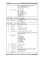
<2>
<2>
<1>
<1>
<1>
<30>
<1>
<1>
<1>
<30>
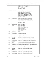
Receive ESC
Audio #1 Volume
Receive ESC
Audio #2 Volume
Reserved
Alarm 5 Mask
Insert Mode
Insert Map
Insert Alarm
Mask
Insert Back Alarm
Mask
Force Terrestrial
Back Alarm
Insert Edit Map
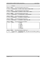
IDR Mode. If not, ignore
-20 to +10, Signed Binary Value in dB
Note: The following two bytes apply only if an IDR OR IBS
interface card is installed and the Receive Mode is set to
IDR Mode. If not, ignore
-20 to +10, Signed Binary Value in dB
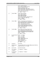
Bit 0 = IBS Satellite Multiframe Fault
Bit 1 = IBS Satellite Frame Fault
Bit 2 = Spare
Bit 3 = IBS Alarm if BER < 10
-03
Bit 4 = IBS Prompt Alarm
Bit 5 = IBS Service Alarm
Bits 6 - 7 = Spares
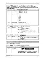
0 = Disable
1 = T1-D4
2 = T1-ESF
3 = PCM-30
4 = PCM-30C
5 = PCM-31
6 = PCM-31C
7 = T1-SLC96
Mapping of Satellite Channels to insert Terrestrial Timeslots
0 = Frame Lock Fault
1 = MultiFrame Lock Fault
2 = CRC Lock Fault. Valid only in T1-ESF and E1 – CRC
enabled
3 = T1 Yellow Alarm Received
4 = E1 FAS Alarm Received
5 = E1 MFAS Alarm Received
6 = E1 CRC Alarm Received
7 = CRC Calculation Fault
Bit 0 = Backward Alarm Received from Satellite
Bits 2 – 7 = Spares
Force D&I Terrestrial Backward Alarm to be Trans
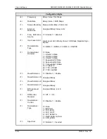
Status Bytes
<1>
<1>
Revision Number
Alarm 1
Decimal Point Implied
Bit 0 = Receive Processor Fault
Bit 1 = Signal Lock Fault
Bit 2 = Receive Satellite AIS Fault
Bit 3 = Rx AGC Input Level Fault
Содержание DMD2401 IBS
Страница 2: ......
Страница 15: ......
Страница 39: ...Operation DMD2401 DMD2401L DMD2401 IBS IDR Satellite Modem 3 16 TM065 Rev 3 3 Figure 3 9 IF Loopback...
Страница 60: ...DMD2401 DMD2401L DMD2401 IBS IDR Satellite Modem User Interfaces TM065 Rev 3 3 4 21...
Страница 199: ...Appendices DMD2401 DMD2401L DMD2401 IBS IDR Satellite Modem 8 12 TM065 Rev 3 3 This Page is Intentionally Left Blank...