background image

MIB Parameters

Appendix F

RADWIN 1000/2000/5000 User ManualVersion  2.5.30p3

F-14

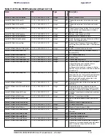
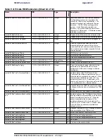
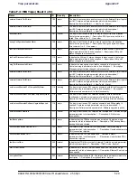
winlink1000OduAgnRealTimeAndDate

1.3.6.1.4.1.4458.1000.1.7.2.3

OctetString

RW This parameter specifies the real time and date   

Format 'YYYY-MM-DD HH:MM:SS' 
(Hexadecimal).
A date-time specification:

field  octets  contents                range
------  -------  -----------                 --------
   1       1-2   year                      0..65536
   2         3     month                  1..12
   3         4     day                      1.. 31
   4         5     hour                     0..23
   5         6     minutes                0..59
   6         7    seconds                0..60
                    (use 60 for leap-second)
   7        8    deci-seconds         0..9

For example  Tuesday May 26  1992 at 1:30:15 
PM EDT would be displayed as: 
07 c8 05 1a 0d 1e 0f 00
( 1992 -5 -26 13:30:15 ) 

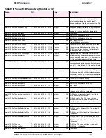
winlink1000OduAgnCurrAlarmLastChang
e

1.3.6.1.4.1.4458.1000.1.7.3.1

Integer

RO

This counter is initialized to 0 after a device reset 
and is incremented upon each change in the 
winlink1000OduAgnCurrAlarmTable (either an 
addition or removal of an entry). 

winlink1000OduAgnCurrAlarmTable

N/A This table includes the currently active alarms. 

When a RAISED trap is sent an alarm entry is 
added to the table. When a CLEAR trap is sent the 
entry is removed. 

winlink1000OduAgnCurrAlarmEntry

N/A Entry containing the details of a currently RAISED 

trap.

winlink1000OduAgnCurrAlarmCounter

RO

A running counter of active alarms. The counter is 
incremented for every new RAISED trap. It is 
cleared after a device reset. 

winlink1000OduAgnCurrAlarmSeverity

RO

Current Alarm severity. 

winlink1000OduAgnCurrAlarmId

RO

Unique Alarm Identifier (combines alarm type and 
interface). The same AlarmId is used for RAISED 
and CLEARED alarms. 

winlink1000OduAgnCurrAlarmIfIndex

RO

Interface Index where the alarm occurred. Alarms 
that are not associated with a specific interface will 
have the following value: 65535. 

winlink1000OduAgnCurrAlarmUnit

RO

Unit associated with the alarm. 

winlink1000OduAgnCurrAlarmTrapID

RO

ID of the raised trap that was sent when this alarm 
was raised. 

winlink1000OduAgnCurrAlarmTimeT

RO

Timestamp of this alarm. This number is in 
seconds from Midnight January 1st 1970. 

winlink1000OduAgnCurrAlarmText

RO

Alarm display text (same as the text in the sent 
trap). 

winlink1000IduAdmProductType

1.3.6.1.4.1.4458.1000.2.1.1

DisplayString

RO

IDU configuration description. 

winlink1000IduAdmHwRev

1.3.6.1.4.1.4458.1000.2.1.2

DisplayString

RO

IDU Hardware Revision. 

winlink1000IduAdmSwRev

1.3.6.1.4.1.4458.1000.2.1.3

DisplayString

RO

IDU Software Revision. 

winlink1000OduAdmNumOfExternalAlar
mIn

1.3.6.1.4.1.4458.1000.2.1.4

Integer

RO

Indicates the number of currently available 
External Alarm Inputs. 

winlink1000OduAdmExternAlarmInTable

N/A This is the External Alarm Inputs table. 

winlink1000OduAdmExternAlarmInEntry

N/A Entry containing the elements of a single External 

Alarm Input.

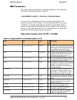
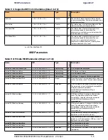
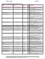
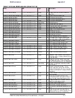
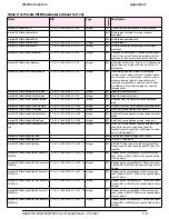
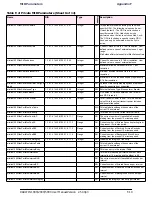
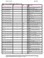
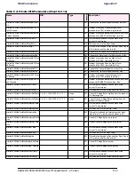
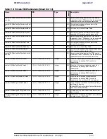
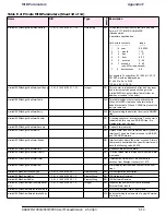
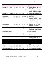
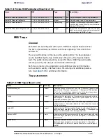
Table F-2: Private MIB Parameters (Sheet 10 of 14)

Name

OID

Type

Access

Description

Содержание WinLink 1000

Страница 1: ...UM 5000 2530 04 11 RADWIN 1000 2000 5000 Broadband Wireless Transmission System User Manual Version 2 5 30p3...

Страница 2: ...he User Manual or any other RADWIN documentation or products You are prohibited from and shall not directly or indirectly develop market distribute license or sell any product that supports substantia...

Страница 3: ...430 USA Tel 1 1 800 444 7234 341 Tel 2 1 201 529 1100 341 Latin America Headquarters Rua Grao Mogol 828 Belo Horizonte MG 30310 010 Brazil Tel 1 55 31 919 76 402 Tel 2 972 54 758 6808 India Headquarte...

Страница 4: ...n a circuit different from that to which the receiver is connected Consult the dealer or an experienced radio TV technician for help Changes or modifications to this equipment not expressly approved b...

Страница 5: ...nd instructions are provided to avoid exposure of wiring to accidental contact with lightning and power conductors in accordance with NEC Sections 725 54 c and 800 30 In all other cases an appropriate...

Страница 6: ...entions Used in this Manual 1 16 Notifications 1 16 Typographical conventions 1 16 General 1 16 Software 1 16 Windows Terminology 1 17 Chapter 2 Site Preparation Planning the Link Site 2 1 Overview 2...

Страница 7: ...he Link Password 4 16 Installing the Link Step 3 Channel Settings 4 17 Installing the Link Step 4 Tx Power and Antenna Settings 4 19 General 4 20 Dual Antennas at Both Sites 4 20 Single Antennas at Bo...

Страница 8: ...etting 6 19 Configuration with Telnet 6 20 Chapter 7 Monitoring and Diagnostics Retrieving Link Information Get Diagnostics 7 1 Link Compatibility 7 3 Reinstalling and Realigning a Link 7 3 The Link B...

Страница 9: ...al Lightning Surge Suppressors and Grounding E 3 Internal ESD Protection circuits E 7 Appendix F MIB Reference Introduction F 1 About the MIB F 1 Terminology F 1 Interface API F 1 Control Method F 1 C...

Страница 10: ...cautions de s curit pendant le montage de ODU I 2 Connecter la terre IDU C I 3 Installation sur pyl ne et mur I 4 Contenu du kit de montage ODU I 4 Montage sur un pyl ne I 5 Montage sur un mur I 6 Mon...

Страница 11: ...UNCONFIGURED LINK 4 3 FIGURE 4 3 LOGIN SCREEN 4 3 FIGURE 4 4 LOGIN SCREEN WITH COMMUNITY OPTIONS VISIBLE 4 5 FIGURE 4 5 UNSUPPORTED DEVICE MESSAGE 4 5 FIGURE 4 6 UNREACHABLE DEVICE MESSAGE 4 6 FIGURE...

Страница 12: ...LOG BOX 7 5 FIGURE 7 3 BASIC PERFORMANCE MONITORING REPORT 7 6 FIGURE 7 4 A TYPICAL PERFORMANCE MONITORING REPORT 7 6 FIGURE 7 5 THRESHOLD CONFIGURATION DIALOG BOX 7 9 FIGURE 7 6 EVENTS LOG DISPLAY 7...

Страница 13: ...DETAILS 5 6 TABLE 5 4 LINK SITE DETAILS SITE A AND SITE B 5 7 TABLE 5 5 STATUS BAR INDICATORS 5 9 TABLE 5 6 LINK CONFIGURATION WIZARD 5 10 TABLE 6 1 ODU MODE CONFIGURATION FOR COMMON 6 11 TABLE 6 2 TE...

Страница 14: ...he RADWIN 1000 2000 radio series offers unmatched performance and carrier class quality with the following features Superior spectral efficiency at 5 10 20MHz and 40MHz channels in the 5 3 5 4 and 5 8...

Страница 15: ...2000 5000 radio series offers WiMAX operators and ISPs a unique highly scalable and cost effective backhaul solution Designed to suit a wide range of topologies RADWIN 1000 2000 5000 is easy to insta...

Страница 16: ...s and eliminate the costly recurring charges from service providers RADWIN 1000 2000 5000 s cost effective solution enables a variety of orga nizations to connect geographically dispersed sites at ran...

Страница 17: ...hanism for error con trol during data transmission When the receiver detects an error in the received information it automatically requests the transmitter to resend the information This process is re...

Страница 18: ...i security recom mendations CCM AES uses a symmetric 128 bit encryption key EK and a nonce and provides both message encryption and authenticat ing signature The nonce mechanism enables the receiver t...

Страница 19: ...o Outdoor Unit ODU The ODU is the radio transceiver of the RADWIN 1000 2000 5000 system It supports two radios for MIMO operation It is available with an integrated antenna Integrated Antenna ODU or w...

Страница 20: ...ted Antenna ODU This ODU has an integrated 370mm 1 2ft flat panel antenna with a gain of 23dBi The ODU contains both the radio and the antenna as a single unit housed in a weatherproof case Connectori...

Страница 21: ...IDU C is designed to be rack mounted One IDU C product is available in release 2 5 30p3 Table 1 1 Available ODU Products Release 2 5 30p3 Part Number Description Form Factor Frequency Bands and Regula...
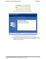
Страница 22: ...links It is a low cost unit intended for both Access applications and Enterprise use Figure 1 7 IDU E front view The IDU E rear panel right to left has a 25 pin Dry Contact Alarms port the two or no...

Страница 23: ...rated with an integrated antenna that is part of the ODU unit or with external antennas connected to the ODU via N type connectors All cables and connections must be connected correctly to reduce RF l...

Страница 24: ...11 below has an integrated or external configuration Figure 1 11 Flat Panel Antenna Integrated or External 1 2ft Flat Panel Dual Polarization Frequency 4 9 6 0 GHz 2 4 2 7 GHz Ext 2 3 2 7 GHz Int 3 3...

Страница 25: ...e RADWIN Man ager has a graphical Microsoft Windows interface and can be run locally and remotely The RADWIN Manager provides Installation Wizard On line monitoring of air interface quality allowing t...

Страница 26: ...N 1000 2000 5000 system PoE devices AC Power Adaptor External Lightning Protection Unit Cables to connect the various system elements Documentation set supplied with RADWIN 1000 2000 5000 The technica...

Страница 27: ...nce Chapter Appendix Subject Audience 2 Site Preparation Site survey team 3 Hardware Instal lation Field technician 4 Link Installation The RADWIN Man ager Installation technician 5 Configuring the Li...

Страница 28: ...ter connected to site A The precise requirements for the managing computer are set out in chapter 3 Hardware Installation RADWIN 1000 2000 5000 supports three connection methods for the man aging comp...

Страница 29: ...s Tools Active Alarms 1 A Note The purpose of a Note is to Draw your attention to something that may not be obvious or coun ter intuitive Emphasize a special feature or peculiarity of the RADWIN 1000...

Страница 30: ...t It will be referred to as a window the main window or the Manager win dow depending on context The top line of icons is the tool bar and provides part of the menu bar functionality with a mouse clic...

Страница 31: ...Windows Terminology Chapter 1 RADWIN 1000 2000 5000 User ManualVersion 2 5 30p3 1 18 Figure1 14 SiteConfigurationwindowwithopenManagementpanel...

Страница 32: ...ment are determined on site 3 Radio Frequency RF survey It is recommended that the installation area be scanned with a spectrum analyzer to identify RF interference so as to determine a clear channel...

Страница 33: ...rvey 1 Mark the two designated installation sites on a topographic map of the area 2 Measure the distance between the sites check that it is within the speci fied range of the RADWIN 1000 2000 5000 3...

Страница 34: ...e locations of the obstructions on the map 3 Determine the location for the ODU having regard for existing rooftop installations and tower space It should be above any obstructions con sidering the Fr...

Страница 35: ...ature should be 0 to 50 C 32 to 122 F at a humidity of up to 90 non condensing Stage 3 RF Survey The RF survey examines the wireless environment of the RADWIN 1000 2000 5000 installation site to deter...

Страница 36: ...hould be grounded during operation In addition The ODU should be earthed by a wire with diameter of at least 12AWG The RADWIN 1000 2000 5000 ODU must be properly grounded to protect against lightning...

Страница 37: ...ments All of RADWIN outdoor units are designed with surge limiting circuits to minimize the risk of damage due to lightning strikes RADWIN recommends the use of additional surge arrestor devices to pr...

Страница 38: ...below A CD containing the RADWIN Manager Quick Start Guide User Manual Link Budget Calculator Label showing the MAC address and the alternative Community string The label is self adhesive You should k...

Страница 39: ...d rear views IDU Package Contents The IDU package contains IDU C see figure 3 4 below 19 rack mounting kit see figure 3 5 below Two DC power plugs for power cables see figure 3 5 below Figure 3 4 IDU...

Страница 40: ...Drill for wall mounting only Cable ties Sealing material Cables and connectors ODU grounding cable 12AWG IDU grounding cable 18AWG ODU IDU cable outdoor class CAT 5e 4 twisted pairs 24AWG Hardware In...

Страница 41: ...ing sections Outdoor installation Mounting the ODU The ODU can be mounted on a pole or a wall In both installations the sup plied mounting kit is used to secure the ODU A RADWIN 1000 2000 5000 link op...

Страница 42: ...antenna onto the pole Refer to Appen dix C Pole and Wall Installation for detailed antenna mounting instructions 2 Follow the mounting instructions supplied with the antenna Mounting the Lightning Pro...

Страница 43: ...the ODU see appendix E 4 Attach the ODU IDU cable to the ODU RJ 45 connector see appendix B for the connector pin out 5 Screw in the cable glands to ensure hermetic sealing of the ODU 6 Secure the cab...

Страница 44: ...unting the IDU C Chapter 3 RADWIN 1000 2000 5000 User ManualVersion 2 5 30p3 3 9 Figure 3 8 IDU C front panel In figure 3 9 we display a perspective view of the IDU C Figure 3 9 IDU C A perspective vi...

Страница 45: ...Indicator LEDs See figure 3 10 B ODU Port RJ 45 connector see table B 1 C 2 LAN Ports Ethernet RJ 45 connector see table B 2 D SFP Port The IDU C is SFP ready E Alarm Ports Standard DB25 female conne...

Страница 46: ...he IDU C has redundant power connection circuits items G and H in figure 3 8 above An enlarged schematic of the power connectors is shown in below Table 3 2 IDU C Front Panel LEDs Name Color Function...

Страница 47: ...t ordered use an outdoor class CAT 5e 24AWG shielded cable See appendix B for Wiring Specifications To connect the ODU to the IDU route the cable from the ODU to the IDU secure the cable along its pat...

Страница 48: ...the ANT 1 connector of the ODU 2 For external bipolar antennas Using a coax cable with N Type connec tors connect the horizontal polarization connector of the antenna to the ANT 2 connector of the ODU...

Страница 49: ...e link 3 On both sides of the link disconnect the antenna connected to the ODU connector ANT 1 Connect the other antenna to connector ANT 1 and fol low the steps 3 to 7 above to align the second anten...

Страница 50: ...y the application are set out in table 4 1 below Requirements common to all systems are Hard disk 1 GB free space Network 10 100BaseT NIC Graphics 1024x768 screen resolution with 16 bit color Microsof...

Страница 51: ...ng the RADWIN Manager application can be used to configure a RADWIN 1000 2000 5000 link Starting the RADWIN Manager To start the RADWIN Manager 1 Connect the managing computer to one of the two LAN po...

Страница 52: ...t connection and that both the the IDU and ODU are switched on and then try again If you do not succeed seek assistance from RADWIN Customer Support 3 Dismiss the command line session 4 Double click t...

Страница 53: ...via an over the air IP address you will receive a warning If you reset the site to which you are connected to factory settings you can lock yourself out of the Link 3 Network login IP address to the...

Страница 54: ...rite and public for read only If Community values were previously defined enter them under Community in the Read Only or Read Write boxes If you are a user with read only permission click the Read Onl...

Страница 55: ...graphic along side the IP Address field Incorrect Password If you type an incorrect password in the Login screen you will see a warn ing graphic alongside the password field Continuing without an IP...

Страница 56: ...le 4 2 RADWIN Manager Offline Functionality Menu level Function Reference Top 1 2 File Log Off Return to Log On dialog Same as Log Off button Exit Exit the RADWIN Manager Same as Exit button Tools Cha...

Страница 57: ...ossible modulation BPSK at 6 5Mbps and will work under the harsh interference condition 2 Link Configuration described in chapter 5 Configuration provides much the same functionality as Installation b...

Страница 58: ...asic information about link sta tus Note An installed and configured link can be returned to installation mode for re installation and configuration from last settings or from factory settings Reversi...

Страница 59: ...u functionality is displayed in table 4 5 The Toolbar buttons are detailed in table 4 6 Table 4 4 Front Panel LEDs Name Color Function IDU With Ethernet only Green Green Red During power up only IDU o...

Страница 60: ...1 name Provides limited configura tion for site Has a path to return to installation mode 2 Configure Site 2 name Provides limited configura tion for site Has a path to return to installation mode Li...

Страница 61: ...uration parameters of an operating wireless link assigns text files for storing alarms statistics and configuration data This button is disabled until a link installation has been completed Link Insta...

Страница 62: ...e Link Overview The Installation wizard has seven steps as shown in table 4 7 below Table 4 7 Link Installation Wizard 1 Wizard welcome 2 System parameters Link ID Site details 3 Channel settings ACS...

Страница 63: ...properly aligned If this box is grayed out you should align the antennas as set out in Connecting and Aligning ODUs Antennas on page 3 13 The Installation Wizard opens Figure 4 9 Link Installation Wi...

Страница 64: ...ID must include at least eight alphanumeric characters Up to 24 characters are allowed You should use a Link ID composed of both alphabetic and numeric characters 2 Enter a Link Name for the link ide...

Страница 65: ...Change button in the System dialog box The Change Link Password dialog box opens Figure 4 11 Change Link Password dialog box 2 Enter the current link password The default link password for a new ODU...

Страница 66: ...onfirm field 5 Click OK 6 Click Yes when asked if you want to change the link password 7 Click OK at the Password changed success message Installing the Link Step 3 Channel Settings RADWIN 1000 2000 5...

Страница 67: ...IN 1000 2000 5000 User ManualVersion 2 5 30p3 4 18 Figure 4 13 Channel Settings Automatic Channel Selection The default frequency for the product is shown To select channels to be used by the link 1 S...

Страница 68: ...s all of the allowable channels for the link Check the channels that can be automatically selected Selecting a new channel causes the system quality to change The Qual ity bar provides an indication o...

Страница 69: ...of two radio transceivers radios The radios make use of algorithms that utilize both polarization and space diversity resulting in enhanced capacity range and link availabil ity The number of antennas...

Страница 70: ...rates RADWIN Manager indicates a case of unbalanced RSS between the two antennas Single Antennas at Both Sites By selecting a single antenna at both sites the ODUs operate with a single radio that is...

Страница 71: ...ll be determined by three factors per band regulation per channel bandwidth antenna gain It appears in figure 4 16 as Max EIRP maxRegTxPower denote the maximum regulatory Tx Power for the equipment al...

Страница 72: ...gurationdialogwithopenedtypeselection 2 Choose the antenna type and required transmission Tx power for the first site and click OK Repeat the process for the second site The Tx power per radio indicat...

Страница 73: ...arameters change warning If inequality above is violated then the following warning window is displayed Figure 4 18 Tx Power Limits The precise relationship between the items in inequality and the win...

Страница 74: ...ble Loss The table in figure 4 18 only shows rates where the maximum Tx Power is the limitation rather than regulations When you close the window of figure 4 18 the change you requested will not be ho...

Страница 75: ...choose a specific modulation rate or use Adaptive To choose a modulation rate 1 Choose Adaptive or one of the available rate see page 1 4 for informa tion about Automatic Adaptive Rate 2 Click Next to...

Страница 76: ...at the Radio Signal Strength RSS is according to expected results as determined by the Link Budget Calculator Caution Installation mode as described above may be re entered using Configuration 1 Confi...

Страница 77: ...Configuration Wizard to redefine the configu ration parameters and fine tune an operational link Both sides of the link are configured simultaneously The following parameters are configured using the...

Страница 78: ...es of the link The Link Status indication bar must be green In the Link Status panel the Status field should show Link Active in green The main window of the RADWIN Manager contains a large amount of...

Страница 79: ...on data This button is disabled until a link installation has been completed Link Installation Performs preliminary configuration of the system This button is disabled after the link is installed Site...

Страница 80: ...rovides limited configura tion for site Has a path to return to installation mode 2 Configure Site 2 name Provides limited configura tion for site Has a path to return to installation mode Installatio...

Страница 81: ...2 Site 2 name Reset Site 2 name ODU Help RADWIN Manager Help View online version of the User Manual Link Budget Calculator Calculator opened in default browser Appendix D Get Diagnostics Information...

Страница 82: ...f the RADWIN Manager Main Window Link details pane The Link details pane on the left is split into three sections The top section summarizes information about the link The two lower panels show basic...

Страница 83: ...to bottom Radio Interface Received Signal Strength RSS in dBm Ethernet Service Ethernet Throughput The numbers are the current calculated throughputs at each site The colored bars with numbers indi c...

Страница 84: ...equency box It shows the link frequency The color of the box indicates the status Green is an active link Red is an inactive link Magenta shows an authentication or compatibility problem Brown shows s...

Страница 85: ...vailable Connection mode to the ODU Over the Air connection using the IP address of the remote unit Local connection direct connection to the IDU without using an IP address Network connection through...

Страница 86: ...30p3 5 10 Configuring the Link Overview The Configuration Wizard has seven steps as shown in table 5 6 below Table 5 6 Link Configuration Wizard 1 Wizard welcome 2 System parameters Link ID Site detai...

Страница 87: ...rrespond ing installation step Configuring the Link Step 1 Start the Wizard In the tool bar of the RADWIN Manager main window click the Link Con figuration button The Link Configuration button is only...

Страница 88: ...ation Wizard System dialog box The System attributes may be edited and the Link Password may be changed exactly as in the corresponding Link Installation step on page 4 14 Click Next to continue Confi...

Страница 89: ...ersion 2 5 30p3 5 13 Figure5 5 ChannelSettingsdialogbox AutomaticChannelSelection Notice that the operating channel is grayed out If you use the Reselect Channel button to change it you will be asked...

Страница 90: ...er ManualVersion 2 5 30p3 5 14 Figure 5 6 Searching for the best operating channel The link will return to the status of figure 5 5 above with a possible change to the operating channel If you work wi...

Страница 91: ...3 Channel Settings Chapter 5 RADWIN 1000 2000 5000 User ManualVersion 2 5 30p3 5 15 Figure 5 7 Channel Settings without automatic channel selection If you click the Operating Channel drop down list th...

Страница 92: ...5 RADWIN 1000 2000 5000 User ManualVersion 2 5 30p3 5 16 Figure 5 8 Channel frequency options Selecting one of the frequencies presented returns you to the status of figure 5 7 with the appropriate ch...

Страница 93: ...ualVersion 2 5 30p3 5 17 Figure 5 9 Choosing an Other Operating Channel frequency The right hand drop down list showing 5 800 allows you to fine tune the frequency in increments of 5MHz within a range...

Страница 94: ...apter 5 RADWIN 1000 2000 5000 User ManualVersion 2 5 30p3 5 18 Configuring the Link Step 4 Tx Power and Antenna Settings Figure 5 10 Transmission Power and Antenna Parameters If you chose to configure...

Страница 95: ...on So far the procedure duplicates the corresponding Installation process on If you choose a different antenna type and click OK you will receive the fol lowing cautionary message Caution In this cont...

Страница 96: ...Loss The procedure is the same as that set out in the Installation procedure on page 4 23 When you have completed making your choice proceed to the Services window Configuring the Link Step 5 Services...

Страница 97: ...Chapter 5 RADWIN 1000 2000 5000 User ManualVersion 2 5 30p3 5 21 Configuring the Link Step 6 Configuration Summary and Exit Figure 5 13 Configuration Wizard Exit Summary Click Done to return to the m...

Страница 98: ...Configuring the Link Step 6 Configuration Summary and Exit Chapter 5 RADWIN 1000 2000 5000 User ManualVersion 2 5 30p3 5 22 Figure 5 14 Main window of the manager after configuration...

Страница 99: ...windows Inventory link hardware and software model details External alarms indicators The Operations dialog offers a doorway to jump into installation mode reverting to factory settings The Site Confi...

Страница 100: ...y View the hardware and software inventory release numbers model identification MAC address Management Configure the IP address Subnet Mask Default Gateway the Trap Destination and VLAN Security Chang...

Страница 101: ...st to open a dialog box 3 Click Apply to save changes In subsequent instructions we will simply say Choose a site to configure on the understanding that the foregoing procedure is implied Viewing Air...

Страница 102: ...ox opens 2 Choose Air Interface see figure 6 3 3 Choose the required Transmit Tx Power Level 4 Click Apply to save the changes Figure 6 3 Changing the Transmit Power Site Management IP Address and VLA...

Страница 103: ...ould be the IP address of the managing computer The events log will be stored at this address 10 Click Apply to save the changes Configuring VLAN Settings VLAN Management enables separation of user tr...

Страница 104: ...The VLAN priority is used for the traffic sent from the ODU to the managing computer Using VLAN for management traffic affects all types of man agement connections local network and over the air 7 Ent...

Страница 105: ...When configuring the NTP Server IP address you should also configure the offset from the Universal Coordinated Time UTC If there is no server available you can either set the date and time or you can...

Страница 106: ...f entering an IP address for the NTP Server click Clear and then enter the new address 6 Set your site Offset value in minutes ahead or behind GMT1 7 To manually set the date and time click Change and...

Страница 107: ...an NTP Server 8 Click OK to return to the Configuration dialog Ethernet Properties Configuring the Bridge Bridge configuration is required in various network topologies such as pro tection 1 1 and ri...

Страница 108: ...dge mode the ODU performs both learning and aging forwarding only relevant packets over the wireless link The aging time of the ODU is fixed at 300 seconds IDU Aging time This parameter controls the I...

Страница 109: ...when attached external equipment does not support auto negoti ation The default setting is Auto Detect To configure the Ethernet Mode 1 From the Configuration menu choose the site to reconfigure The S...

Страница 110: ...menu to choose the maximum Information Rate 4 Choose Other to define the throughput with 1 Kbps resolution 5 Choose Not Limited for the highest information rate possible for the link conditions and se...

Страница 111: ...atures Chapter 6 RADWIN 1000 2000 5000 User ManualVersion 2 5 30p3 6 13 Figure 6 10 Inventory Screen Security Features The Security dialog enables you to change the Link Password and the SNMP Communit...

Страница 112: ...sed by the ODU to issue traps The Community string must be entered at login The user must know the password and the correct Community string to gain access to the system A user may have read only priv...

Страница 113: ...g box is available from the Configuration Security tab Both read write and read only communities must be defined On logging on for the first time use the following as the current Commu nity For Read W...

Страница 114: ...s supplied with the product and should be kept in a safe place If both the read write Community and the alternative Community key are unavailable then an alternative Community key can be obtained from...

Страница 115: ...s 3 In the Configuration dialog box click the Buzzer button The button tog gles between on and off The tone is disabled To restore the alignment tone 1 Choose a site The Configuration dialog box opens...

Страница 116: ...gure 6 14 External Alarm Configuration 2 Choose an alarm and set its mode to Enabled or Disabled 3 Enter a description of the alarms in the text field 4 Click Apply to save 5 Click OK to exit from the...

Страница 117: ...onfiguration or reset to fac tory defaults To reset the link preserving current configuration 1 From Maintenance on the main window reset the remote unit 2 From Maintenance on the main window reset th...

Страница 118: ...nagement Displays IP Subnet Gateway Traps table display link Displays State Link ID Channel BW RSS TSL Frequency ACS DFS Rate ARA Distance display Ethernet Displays Bridge Mode Aging time Port table S...

Страница 119: ...e 0 off 1 on set name new name Set the name of the link set location new location Set the name of the location Set contact new contact Set the name of the site manager set Ethernet port MNG LAN1 LAN2...

Страница 120: ...splay PM interface AIR LAN1 LAN2 TDM1 TDM2 TDM3 TDM4 interval current day month set ip ipaddr subnetMask gateway set trap index 1 10 ipaddr port 1 65535 set readpw writePasswd newPasswd set writepw wr...

Страница 121: ...eving link information Link compatibility issues Reinstalling and realigning a link Performance monitoring Troubleshooting Replacing an ODU Restoring to factory setup Retrieving Link Information Get D...

Страница 122: ...checked 3 Click File Path to specify the folder in which you want to save the file and then click Start to save the information The file is saved in the specified folder as Diagnostics Informa tion t...

Страница 123: ...t software versions were detected allow ing limited operation The message is that a software upgrade required versionsIncompatibility different software versions were detected that are incompatible Yo...

Страница 124: ...s and climate condi tions For full details see appendix D Performance Monitoring RADWIN 1000 2000 5000 Performance Monitoring constantly monitors traf fic over the radio link and collects statistics d...

Страница 125: ...te in which folder and under what name the monitor log file is to be saved 6 Set the time interval for adding data to the file 7 Click OK to save the file Viewing Performance Reports The Performance M...

Страница 126: ...ft panel and click the Get Data toolbar button For example if you choose Site A Air and Current you will be offered a report looking like this Figure 7 4 A typical Performance Monitoring Report You ca...

Страница 127: ...s well as Specific data per Interface type e g TX and RX bytes for Ethernet For the Air Interface user defined thresholds data are collected Refer to table 7 3 and table 7 4 in Performance Monitoring...

Страница 128: ...were stored e g due to clock changes within the interval or power up reset Air Interface PM Data Max RSL The maximum of the receive signal level mea sured in dBm Min RSL The minimum of the receive si...

Страница 129: ...50 For links with Ethernet only service 8 threshold is recommended If there are no problems during the interval then for that threshold the recom mended BBER value should be 0 Since the system provid...

Страница 130: ...tions and events Alarms traps are displayed in the Events Log in the lower panel of the main window The Events Log may be saved as a text file The Events Log includes the following fields Sequential n...

Страница 131: ...was not finished due to connec tion issues Warning Factory setting failed due to connectivity problem to tar get Target will not be reset Cannot Write to Monitor file There is not enough space on the...

Страница 132: ...ences dialog box appears 2 Click the Events Tab The Manager identified a newer ODU release at both sites Warning The Manager identified a newer ODU release at the local_site_name site Warning Newer Ve...

Страница 133: ...p background color Click Background Color to change the text background To reset the event colors Click Reset Settings to return to the default color settings Saving the Events Log You can save record...

Страница 134: ...Advanced tab from the Preferences dialog Just click the Restore Defaults button followed by OK Active Alarms Upon setting a trap destination applicable events are reported as active alarms to the user...

Страница 135: ...dication about the power loss just before powering off A Dying Gasp circuit identifies the power failure at a minimum interval of 20 milliseconds before the ODU or IDU powers off During that interval...

Страница 136: ...re that configura tion using Site A Restore Table 7 7 LED fault indicators LED Status Remedy PWR Off Check that AC adapter is connected to the IDU E and the AC power outlet IDU Orange Check that the I...

Страница 137: ...ng the Site A Advanced option 2 Activate the second ODU and carry out a new Installation Online Help Online help can be accessed from the Help menu on the main screen of the RADWIN 1000 2000 5000 Mana...

Страница 138: ...hnical Specifications Configuration Architecture ODU Outdoor Unit with Integrated Antenna or Connector ized for External Antenna IDU Indoor Unit for service interfaces or PoE device for Ethernet only...

Страница 139: ...z channel bandwidth and 6dBi antenna assembly gain 5 470 5 725 GHz excluding 40 MHz channel bandwidth and 6dBi antenna assembly gain 5 470 5 725 GHz including 40 MHz channel bandwidth and 6dBi antenna...

Страница 140: ...dBi assembly 5 725 5 825 GHz 23 8 dBm 28 dBi Dish 26 4 dBm 22 5 dBi Integral Flat 26 4 dBm 23 5 dBi External Flat 29 4 dBm 6 dBi assembly 24 4 dBm 14 dBi External Flat 24 dBm 16 5 dBi External Flat 29...

Страница 141: ...Rate Single Antenna in the 5 8 GHz spectrum band Mbps 13 5 27 40 5 54 81 108 121 5 135 Rate Dual Antenna Mbps 13 26 39 52 78 104 117 130 Rate Dual Antenna in the 5 8 GHz spectrum band Mbps 27 54 81 10...

Страница 142: ...2 W x 4 5 1 7 H x 21 8 3 D cm 1 5 kg 3 3 lbs IDU E 22 8 7 W x 4 4 1 7 H x 17 6 7 D cm in 0 5 Kg 1 1 lbs Power Feeding Dual feeding 20 to 60 VDC AC DC converter is available Power Consumption 35 W IDU...

Страница 143: ...ranges that comply with ETSI FCC and IC regulations The RADWIN 1000 RW 1020 0150 RADWIN 2000 RW 2020 0150 is avail able only in the 2 4GHz frequency band range that complies with FCC and IC regulation...

Страница 144: ...e following table shows the connector pinout User Port Connectors LAN Port The LAN 10 100BaseT interface terminates in an 8 pin RJ 45 connector wired in accordance to table B 2 Table B 1 ODU IDU Conne...

Страница 145: ...DWIN 1000 2000 5000 User ManualVersion 2 5 30p3 B 2 Table B 2 Fast Ethernet Connector Pinout Pin Signal Function 1 TD Transmit Data positive 2 TD Transmit Data negative 3 RD Receive Data positive 6 RD...

Страница 146: ...DU C Alarm Connector Dry Contact I O Description Pin Input 1 Positive 14 Input 1 Negative 15 Input 2 Positive 16 Input 2 Negative 17 Input 3 Positive 18 Input 3 Negative 19 Input 4 Positive 20 Input 4...
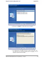
Страница 147: ...inal Note Use an external current limit resistor to limit the current at the output relays to 1 Ampere Such resistor is not required if the equipment connected to the IDU supports current limiting to...

Страница 148: ...ting Kit Contents Table C 1 Bill of Materials ODU mounting kit Item Qty Large Clamp see figure C 1 1 Small Clamp see figure C 2 1 Arm see figure C 3 1 Screw hex head M8x40 4 Screw hex head M8x70 2 Was...

Страница 149: ...Mounting RADWIN 1000 2000 5000 on a pole Appendix C RADWIN 1000 2000 5000 User ManualVersion 2 5 30p3 C 2 Mounting RADWIN 1000 2000 5000 on a pole Figure C 4 Mounting on a pole...

Страница 150: ...2000 5000 User ManualVersion 2 5 30p3 C 3 Mounting RADWIN 1000 2000 5000 on a Wall Figure C 5 Mounting on a Wall Mounting an External Antenna Optional external antennas can be mounted on a pole The e...

Страница 151: ...a default value that cannot be changed Product or Regulation and Band Channel Bandwidth fixed to 20 MHz for RADWIN 1000 2000 5000 Tx Power maximum Tx power per modulation is validated Antenna Type ca...

Страница 152: ...range for which at the highest air rate for which this relation ship is true In a link with adaptive rate this will be the actual behavior MaxRange for a given air rate is the largest range for which...

Страница 153: ...n the Link Budget Calculator from the CD 1 Insert the RADWIN Manager CD into the drive on the managing com puter In the window which opens click the Link Budget Calculator option 2 If the CD autorun a...

Страница 154: ...nning the Link Budget Calculator Appendix D RADWIN 1000 2000 5000 User ManualVersion 2 5 30p3 D 4 Figure D 1 Accessing the Link Budget Calculator However invoked your browser displays the following pa...

Страница 155: ...Running the Link Budget Calculator Appendix D RADWIN 1000 2000 5000 User ManualVersion 2 5 30p3 D 5 Figure D 2 Link Budget Screen...

Страница 156: ...000 2000 5000 1 Choose a product from the drop down list or choose a Regulation and Band Note Microsoft Internet Explorer users may see a warning message like this Click the yellow bar and follow the...

Страница 157: ...Running the Link Budget Calculator Appendix D RADWIN 1000 2000 5000 User ManualVersion 2 5 30p3 D 7 Figure D 3 Product selector 2 Enter the radio details Note that Rate is chosen from a drop down list...

Страница 158: ...Ethernet Rate The Fade margin is the minimum required for LOS conditions For degraded link conditions a larger Fade margin should be used The EIRP is given in dBm and Watts 3 If the required range bet...

Страница 159: ...Running the Link Budget Calculator Appendix D RADWIN 1000 2000 5000 User ManualVersion 2 5 30p3 D 9 Figure D 5 Calculation of distance from site coordinates...

Страница 160: ...0 5000 User ManualVersion 2 5 30p3 D 10 4 Located to the right of the green Coordinates button is a dropdown list of Climactic C Factor values Figure D 6 Climactic C Factors For help about what these...

Страница 161: ...g the Link Budget Calculator Appendix D RADWIN 1000 2000 5000 User ManualVersion 2 5 30p3 D 11 Figure D 7 Climactic C Factor description In figure D 8 we display a map of the world showing C Factor co...
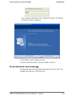
Страница 162: ...2000 5000 ODUs are optimally aligned Ethernet Rate maximum throughput available for the chosen parameter combination Antenna height for LOS the minimum antenna height required for line of sight operat...

Страница 163: ...and atmo spheric conditions weather conditions large bodies of water and other reflectors and absorbers of electromagnetic energy The Fresnel zone provides us with a way to calculate the amount of cl...

Страница 164: ...or reliabil ity point to point links are designed to have at least 60 of the first Fresnel zone clear to avoid significant attenuation The concept of the Fresnel zone is shown in figure D 9 above The...

Страница 165: ...ounding for each IDU and ODU External Primary Surge Suppressor units and grounding for the out door cable Internal ESD protection circuits over the Power Telecom lines Grounding for Antenna Cable A Gr...

Страница 166: ...rovide a good Lightning Discharge path since it can not tolerate the high Lightning Current surges To provide an alternate Lightning Discharge path the ODU and antenna grounding posts should be connec...

Страница 167: ...5 30p3 E 3 The device should be permanently connected to ground External Lightning Surge Suppressors and Grounding A Grounding Kit and Surge Arrestor Unit must be located near the ODU and properly gro...

Страница 168: ...and Grounding Appendix E RADWIN 1000 2000 5000 User ManualVersion 2 5 30p3 E 4 Figure E 3 Grounding a typical wall installation The next figure shows a close up of the rear of grounded ODU Figure E 4...

Страница 169: ...Ground bar for proper surge protection The system wiring is installed with RJ 45 type connectors that can feed directly into the chassis without having to cut splice or route through awk ward strain r...

Страница 170: ...ent water from penetrating with the strain reliefs facing the ground 2 Remove the cover by unscrewing the front of the unit 3 Mount the unit to an outside surface using the two mounting holes 4 Connec...

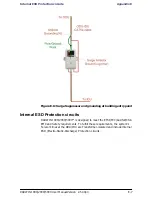
Страница 171: ...grounding at building entry point Internal ESD Protection circuits RADWIN 1000 2000 5000 is designed to meet the ETSI FCC Aus NZ CSA EMC and Safety requirements To fulfill these requirements the syst...

Страница 172: ...rivate MIB used by RADWIN Terminology The following terms are used in this appendix In addition the MIB uses internally the older notions of Local site and Remote site where this manual would use site...

Страница 173: ...some of the configuration parameters additional action must be taken before the new value is loaded Please refer to the operation in the parameters description Some of the MIB parameters values are pr...
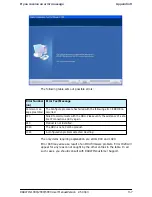
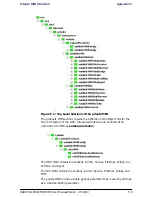
Страница 174: ...Object IDs for the two form factors of the ODU Integrated Antenna and Connectorized referred in the MIB as external antenna The ODU MIB contains the sections Admin Service Ethernet Bridge Air PerfMon...

Страница 175: ...sion of the hardware interface ifType 1 3 6 1 2 1 2 2 1 3 Integer RO The type of interface distinguished according to the physical link protocol s immediately below the network layer in the protocol s...

Страница 176: ...immediately winlink1000OduAdmResetCmd 1 3 6 1 4 1 4458 1000 1 1 5 Integer RW Reset Command A set command with a value of 3 will cause a device reset The read value is always 0 winlink1000OduAdmAddres...

Страница 177: ...the SNMP agent winlink1000OduAdmLinkPassword 1 3 6 1 4 1 4458 1000 1 1 21 DisplayString RW Link Password This parameter always returns when retrieving its value It is used by the Manager application t...

Страница 178: ...tted by this port winlink1000OduBridgeTpPortInBytes 1 3 6 1 4 1 4458 1000 1 4 4 3 1 10 1 Counter RO Number of bytes received by this port winlink1000OduBridgeTpPortOutBytes 1 3 6 1 4 1 4458 1000 1 4 4...

Страница 179: ...vail enabled A change is effective after link re synchronization Valid values disabled 0 enabled 1 winlink1000OduAirChannelsAvail 1 3 6 1 4 1 4458 1000 1 5 18 1 4 Integer RO Channel state Product spec...

Страница 180: ...e Synchronization sync status winlink1000OduAirHssExtPulseStatus 1 3 6 1 4 1 4458 1000 1 5 40 4 Integer RO Hub Site Synchronization external pulse detection status winlink1000OduAirHssExtPulseType 1 3...

Страница 181: ...r RO Total Transmit Power in dBm This is a nominal value While the actual transmit power includes additional attenuation winlink1000OduPerfMonCurrTable N A This table defines keeps the counters of the...

Страница 182: ...e sh2Exceed 1 3 6 1 4 1 4458 1000 1 6 4 1 4 Gauge RO Number of seconds Receive Signal Level exceeded the RSL2 threshold in the last 15 minutes winlink1000OduPerfMonAirCurrMinTSL 1 3 6 1 4 1 4458 1000...

Страница 183: ...exceeded the BBER1 threshold per Day winlink1000OduPerfMonEthCurrTable N A This table defines keeps the counters of the current 15 min interval winlink1000OduPerfMonEthCurrEntry N A This is an entry...

Страница 184: ...nder TDM backup link the parameter indicates whether the backup link was active winlink1000OduPerfMonTxThresh1 1 3 6 1 4 1 4458 1000 1 6 20 Integer RW When the Transmit power exceeds this threshold a...

Страница 185: ...e reset winlink1000OduAgnCurrAlarmSeverity RO Current Alarm severity winlink1000OduAgnCurrAlarmId RO Unique Alarm Identifier combines alarm type and interface The same AlarmId is used for RAISED and C...

Страница 186: ...Integer RO A bitmap describing the number of TDM trunks that can be opened in the current configuration The values take into account the IDU hardware configuration the air rate and the installation r...

Страница 187: ...or aging Note that for this parameter to be effective the ODU must be configured to HUB mode A change is effective immediately winlink1000IduTdmTxClockAvailStates 1 3 6 1 4 1 4458 1000 2 6 1 1 Integer...

Страница 188: ...valuated TDM service bit mask Setting this parameter to value that is bigger than the activated TDM service bit mask will execute the evaluation process for 30 seconds Setting this parameter to 0 will...

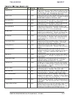
Страница 189: ...ce reset and is incremented upon each element constant write operation via SNMP or Telnet Table F 3 MIB Traps Sheet 1 of 4 Name ID Severity Description trunkStateChanged 1 normal Indicates a change in...

Страница 190: ...escription Channel scanning in progress incompatiblePartner 16 critical Indicates that configuration problem was detected and that link installation is required to fix it Contains a single parameter w...

Страница 191: ...s its description 1 Description External Alarm 4 User Text Alarm swVersionsMismatchFullCompatibilityAlarm 114 warning The trap is sent in case SW versions mismatch with full link functionality Contain...

Страница 192: ...to connected s 2 s Is the Eth mode speed duplex externalAlarmInPort3Clear 211 normal This Trap is sent every time an External Alarm Input fault of port 3 is cleared Contains a single parameter which i...

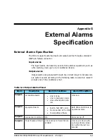
Страница 193: ...stem events according to the following table An alarm is raised if at least one of the conditions is met Table G 1 Output Alarms Pinout Alarm Description Alarm On Conditions Alarm Off Condition Output...

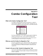
Страница 194: ...you through the Wizard It also provides help for common problems encountered during the configuration Who may use the Combo Configuration Tool The Combo Configuration Tool is a password protected util...

Страница 195: ...a double click The Combo Configuration Tool is a Wizard which guides you through the process of changing the frequency band Before using the Combo Configuration Tool Before starting Obtain the IP addr...

Страница 196: ...figuration Tool Appendix H RADWIN 1000 2000 5000 User ManualVersion 2 5 30p3 H 3 2 Click Next The window below is displayed 3 Enter the ODU IP address and password 4 Click Next The following progress...

Страница 197: ...2 5 30p3 H 4 Upon completion the following screen is displayed The checked item is the currently configured frequency band 5 Check the box with the required frequency band If you do not see the requir...

Страница 198: ...User ManualVersion 2 5 30p3 H 5 6 Otherwise click Next The following window is displayed 7 If the legal notice is acceptable click the I accept radio button and then click Next Two successive progres...

Страница 199: ...of the configuration process the following termination window is displayed 8 Click Finish to exit the Wizard as shown 9 Repeat the whole process for the second ODU in the link If you receive an error...

Страница 200: ...for any reason not caught by the other entries in the table In all such cases you should consult with RADWIN Customer Support Error Number nn Error Text Message Common mes sage preamble The Configure...

Страница 201: ...tation une prise de courant avec une protection de terre En outre La cosse de masse sur l IDU C doit tre constamment connect e la protection de terre par un c ble de diam tre de 18 AWG ou plus Le mat...

Страница 202: ...vec Windows 2000 ou Windows XP Pr cautions de s curit pendant le montage de ODU Avant de connecter un c ble l ODU la borne protectrice de masse visse de l ODU doit tre connect e un conducteur externe...

Страница 203: ...nstamment connect la terre Prudence Ne pas se placer en face d une ODU sous tension Prudence Les appareils sont pr vus pour tre install s par un personnel de ser vice Les appareils doivent tre connect...

Страница 204: ...ne ou un mur Contenu du kit de montage ODU Le kit de montage ODU comprend les pi ces suivantes une grande clame voir figure I 1 une petite clame voir figure I 2 un bras voir figure I 3 quatre visses...

Страница 205: ...Montage sur un pyl ne Appendix I RADWIN 1000 2000 5000 User ManualVersion 2 5 30p3 I 5 Montage sur un pyl ne Figure I 4 Montage sur un pyl ne...

Страница 206: ...Montage sur un mur Appendix I RADWIN 1000 2000 5000 User ManualVersion 2 5 30p3 I 6 Montage sur un mur Figure I 5 Montage sur un mur...

Страница 207: ...ixation en m tal Pour installer une antenne externe sur un pyl ne 1 Attacher le support en U l arri re de l antenne en utilisant quatre ron delles plates quatre rondelles lastiques et quatre crous hex...

Страница 208: ...Repeat Request 1 4 B backup configuration file 6 2 ODU replacement 7 16 Beeper mute 6 17 muting and restoring 6 3 restore 6 17 Bridge mode Telnet commands 6 21 Buzzer see Beeper C Changing link passwo...

Страница 209: ...s D 2 Climactic C Factors D 10 described D 1 Fresnel Zone described D 13 Internal data D 1 Running D 3 User input D 1 Lightning and Grounding Guidelines E 1 Link Budget Calculator see LBC Configuratio...

Страница 210: ...assword 4 7 Events Log 5 8 Installing 4 1 Main window 5 1 Details pane 5 6 Main menu 5 3 Toolbar 5 2 main window 4 5 Monitor pane 5 7 Ethernet Service 5 7 Radio Interface 5 7 Radio signal strength 5 7...

Страница 211: ...ring Bridge 6 9 Maximum information rate 6 12 Ports Mode 6 11 Ethernet PropertiesIDU Aging time 6 10 Functions 6 2 Inventory 6 12 Menu bar 6 2 Setting the date and time 6 7 View Air Iinterface details...

Отзывы: