

Operating Instructions
1997 Radionics All rights reserved
The Radionics logo is a registered trademark of Radionics,
1800 Abbott Street, Salinas, CA 93901, USA
74-07649-000-B 01/97
D9024/D10024 Installation
Page 17 of 17
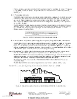
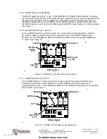
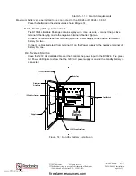
E. Normal Operation
In normal operation, the D9024 or D10024 indicates three conditions: normal power and polling, trouble,
and alarm. If an alarm or fault condition is detected, the panel responds with a buzzer, an LED indication
of the type of condition, an LED indication of the zone/area of the condition, and detailed information on
the alphanumeric display. If more than one alarm or fault is detected, the alphanumeric display will
automatically scroll through the first four.
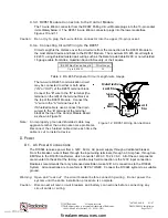
E.1. Normal Power and Polling Activity
Under normal operation the green
AC Power
LED at the right of the indicator display is lit. If the 120
V
AC power supply fails, it flashes. If the standby batteries fail, it goes out.
E.2. Trouble or Fault Conditions
If a device fails to respond, is disabled, the response is not within normal parameters, or the system
detects a fault, the amber
System Trouble
or
Fault
LED lights. In addition, the amber TROUBLE
LED in the ZONE/AREA section of the panel will light to indicate the location, the panel’s internal
buzzer will sound, and the alphanumeric display will provide detailed information.
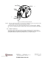
E.3. Alarm Conditions
The red
Alarm
LED at the left of the indicator display flashes to indicate the system has detected a
fire condition, or “Manual Alarm” has been pressed.
In a fire condition, the ZONE/AREA ALARM LED(s) will also light, indicating the alarm location(s),
and the alphanumeric display will provide detailed information.
E.4. Resetting the System
If the keypad has been disabled, pressing the Silence or Reset keys will result in a message on the
alphanumeric display asking for the level two passcode.
E.4.a. Trouble/Fault Reset
To acknowledge the event, press the
Trouble Silence
key to mute the internal buzzer. (Under
certain circumstances, the system may override the mute.) The amber
Trouble Silenced
LED
will light to indicate that condition. Press the
System Reset
key.
E.4.b. Alarm Reset
Note that the panel can only be reset from a fire condition if the alarms have been silenced.
To acknowledge an alarm, press the
Alarm Silence
key, which silences or resounds (toggles on
and off) all alarm devices external to the FACP. The amber
Alarm Silenced
LED lights to
indicate that condition. To resound the alarms, press the
Alarm Silence
key. Press the
System
Reset
key.
For Assistance Contact:
A copy of these instructions shall be framed and placed adjacent to the D9024 or D10024 control
unit.
www.PDF-Zoo.com
firealarmresources.com


