Radionics D9024 Скачать руководство пользователя страница 11

1997 Radionics                All rights reserved

The Radionics logo is a registered trademark of Radionics,

    1800 Abbott Street, Salinas, CA  93901, USA

74-07649-000-B        01/97
D9024/D10024 Installation

Page 11 of 17

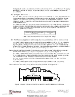
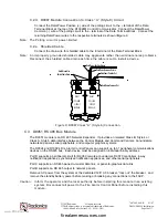
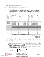
C.3.a.  D9051 Module Installation

The D9051 plugs into 

Ports B, C

, or

 D

  on the D9024M or D10024M Control Module.  These are

the three ports on the left side of the Control Module.  Depending on the circuit configuration and

the panel, both the D9051 and the D9067 Circuit Modules may be mounted to the same four

attachment points above a 10- pin ribbon socket.  Where both are mounted at the same point,

the D9067 attaches next to the Control Module and the D9051 mounts above it on 30 mm pillars.

See Figure 7.

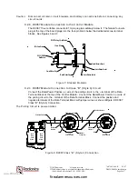
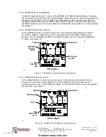
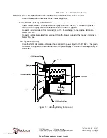
C.3.b.  D10024 Attachment Points

On the D10024 

Ports B, C

, and 

D

 are below the 10-wire ribbon sockets labeled PL_LOOP3,

PL_LOOP4, AND PL_LOOP5, which are connecting points for the D9067 Polling Circuit

Modules.  On the D10024M the D9051 and D9067 modules can mount together above 

Ports


B,

C

, and 

D

.  

See Figure 10.

COM

24V.AUX.

0V

.

COM

N/C

+2

4V

.

N/O

N/C

N/O

AUX RELAYS

RELAY 1

RELAY 2

 LOOP

+

-

+

E

-

5

+

-

OUTPUTS

SOUNDER

1

EA

RT

H

2

-D

C

+D

C

-

+

E

-  LOOP

4

+

E

-

+

+

3

 LOOP

-

+

E

 LOOP

-

2

-

+

E

 LOOP

+

-

1

D10024 Control Module

8-Wire

Ribbon Socket

10-Wire Ribbon Socket

D9051

D9067

D9067

PORT-C

PORT-B

PL_LOOP4

PL_LOOP3

D9051 Module

Connected to

Port "D"

D9067 Connected
to PL_LOOP1

Mounting Screw Attachment Point

Port"C"

Port"B"

Port"D"

Figure 10: D10024 Control Module Configuration

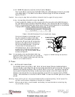
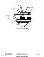
C.3.c.  D9024 Attachment Ports

On the D9024 

Ports B, C

, and 

D

 are the three ports on the left side of the board.  

Port B

  is

below the 10-wire ribbon socket labeled PL_LOOP3 and 

Ports C

 and 

D

 are reserved for

peripheral devices only.  On the D9024 the D9051 and the D9067 modules may mount together

above 

Port B.  See Figure 11.

+

SOUNDER
OUTPUTS

E

+ -

+ -  LOOP

5

 LOOP

E

+ -

+ -

4

E

+ -

+

-  LOOP

3

-

E

-

+

 LOOP

2

+

-

E

-

+

 LOOP

1

N/O

RELAY 2

N/C

24V.AUX.

0V

.

+2

4V

.

N/O

COM

N/C

RELAY 1

AUX RELAYS

COM

OUT

IN

-D

C

1

2

EA

RT

H

+D

C

D9051 Module

Port "D"

D9024 Control Module

8-Wire

Ribbon Socket

10-Wire Ribbon Socket

D9051

D9067

D9067

PORT-C

PORT-B

Port "C"

Mounting Screw Attachment Point

Figure 11: D9024 Control Module Configuration

www.PDF-Zoo.com

firealarmresources.com

Содержание D9024

Страница 1: ...o provide reasonable protection against harmful interference in a commercial installation This equipment generates uses and can radiate radio frequency energy and if not installed in accordance with t...

Страница 2: ...stallation 8 C 2 b D9067 Module Connection to the Control Module 9 C 2 c D9067 Module Connection to Class B Style 4 Circuit 9 C 2 d D9067 Module Connection to Class A Style 6 Circuit 10 C 2 e Shielded...

Страница 3: ...Circuit Module Installation 8 Figure 7 Stacked Modules 9 Figure 8 D9067 Class B Style 4 Connection 9 Figure 9 D9067 Class A Style 6 Connection 10 Figure 10 D10024 Control Module Configuration 11 Figur...

Страница 4: ...ircuits use types FPL FPL R or FPLP cable as applicable per NEC Article 760 A 1 Semi flush Mounting 1 Prepare an opening in the wall 20 x 20 x 5 1 2 2 Remove the knockouts asnecessary forwiring condui...

Страница 5: ...nts other than attention to the wire gauge Under extremely noisy conditions twisted pair wire is recommended to reduce interference If EMI is a problem use shielded cable being careful to ground the d...

Страница 6: ...ge B 3 Notification Appliance Indicating Device and Output Circuit Connections The D9024 and D10024 each has four power limited and supervised Class B Style W indicating circuits The terminal blocks f...

Страница 7: ...ogrammed into the panel and are stored in the Central Processing Unit CPU to each analog device These levels can be altered through the front panel or PC programming Each device is programmed for Alar...

Страница 8: ...as shown in Figure 6 COM 24V AUX 0V COM N C 24V N O N C N O AUX RELAYS RELAY 1 RELAY 2 OUT IN LOOP E 5 OUTPUTS SOUNDER 1 EARTH 2 DC DC E LOOP 4 E 3 LOOP E LOOP 2 E LOOP 1 D10024 Control Module 8 Wire...

Страница 9: ...e Ribbon Socket 8 wire Ribbon Socket Figure 7 Stacked Modules C 2 c D9067 Module Connection to Class B Style 4 Circuit Connect the Data Power Positive wire of the polling circuit to the terminal of th...

Страница 10: ...on Return Data Power Positive Out Data Power Common Out Figure 9 D9067 Class A Style 6 Connection C 3 D9051 RS 485 Bus Module The D9051 module is an RS 485 Network Expander It provides an isolated Cla...

Страница 11: ...above Ports B C and D See Figure 10 COM 24V AUX 0V COM N C 24V N O N C N O AUXRELAYS RELAY1 RELAY2 LOOP E 5 OUTPUTS SOUNDER 1 EARTH 2 DC DC E LOOP 4 E 3 LOOP E LOOP 2 E LOOP 1 D10024 Control Module 8...

Страница 12: ...e top of the D9051 Module Connect the A wire to the A terminal next to it If Shielded cable is used connect the drain wire s to the E terminal of the terminal block at the top of the Control Module Bo...

Страница 13: ...hem in the same conduit and keep them apart inside the enclosure Connect the ground wire to the ground input middle terminal on 3 Amp fuse holder See Figure 13 The 120V neutral and line wires connect...

Страница 14: ...300 A 300 mA x Qty 300 A 300 mA x Qty D327 320 A 320mA x Qty 320 A 320 mA x Qty 320 A 320 mA x Qty D329 280 A 280mA x Qty 280 A 280 mA x Qty 280 A 280 mA x Qty Other devices connected to the system n...

Страница 15: ...No one to the negative terminal of battery N o two Connect the red wire lead from terminal 6 on the Power Supply to the positive terminal of battery No two Connect the black wire lead from terminal 7...

Страница 16: ...LARM LED ALARM SILENCED LED AC POWER LED TROUBLE SILENCE KEY ALARM SILENCE KEY FIRE DRILL KEY 0 1 2 4 3 5 7 8 9 CHANGE System Trouble A N SHIFT 1 3 Alarm B O C P LED DISPLAY 7 Earth Fault 5 4 6 Troubl...

Страница 17: ...el s internal buzzer will sound and the alphanumeric display will provide detailed information E 3 Alarm Conditions The red Alarm LED at the left of the indicator display flashes to indicate the syste...

Отзывы: