background image

Model: Ei168

User Manual

for use with

Smoke & Heat Alarms

Contains vital information on the products operation and installation. Read
and retain carefully. If you are just installing this product 

the manual

MUST be given to the householder.

B A S E

Содержание Ei168

Страница 1: ...evans Limited secure online store at www DeafEquipment co uk DeafEquipment co uk Solutions to improve the quality of life S So ol lu ut ti io on ns s t to o i im mp pr ro ov ve e t th he e q qu ua al li it ty y o of f l li if fe e Connevans ...

Страница 2: ...ual for use with Smoke Heat Alarms Contains vital information on the products operation and installation Read and retain carefully If you are just installing this product the manual MUST be given to the householder B A S E ...

Страница 3: ...ATINGTHE REPEATER FUNCTION 5 TROUBLESHOOTING RF LINK 6 LIMITATIONSOF RADIO COMMUNICATIONS 7 CHECKING MAINTAININGYOUR SMOKEALARMSYSTEM 8 GETTINGYOUR RadioLINK BASESERVICED 9 FIVEYEARGUARANTEE 10 TECHNICALSPECIFICATION 11 RadioLINKACCESSORIES 1 2 3 7 8 10 11 13 13 14 17 Page ...

Страница 4: ...the Ei168 RadioLINK Base This will auto matically activate the rechargeable back up cells Repeat this procedure for all alarms in the system see page 5 1 3 To House Code insert a small screwdriver into the house code switch slots of each unit in succession This must be completed within 15 minutes to activate the house code mode and ensure zoned interconnection see page 6 It is essential that the R...

Страница 5: ...ase will normally be wired to the nearest mains circuit in the ceiling usually the lighting circuit provided unswitched live is available The Smoke Heat Alarm is then slid on to the RadioLINK Base rather than to its normal mounting plate As many as 12 units can be interconnected in this way It is essential to house code the RadioLINK Bases to ensure they will not accidently signal to nearby system...

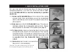
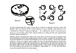
Страница 6: ...lying with the advice in the Smoke Heat Alarm instruction leaflet 2 Disconnect the AC mains supply from the circuit that is going to be used 3 Carefully align the RadioLINK Base and screw into place as shown in figure 1 It is advisable at this time to use only one screw as shown as it allows the base to be rotated later if required If you use only one screw ensure the base is secure on the ceiling...

Страница 7: ...e surface a position the mounting plate so the cable trunking is as shown in figure 3 b Carefully cut and trim the knockouts in the RadioLINK Base side walls to blend with the contours of the trunking Important Only cut the thinned down knockout section and leave the top intact as shown There is only one position suitable for the surface wiring to enter the alarm 6 The house wiring must then be co...

Страница 8: ...will minimize their effect on the radio aerial 7 Replace the wiring cover 8 Remove the required Smoke Heat Alarm from the box discard the mounting plate supplied Carefully line up the smoke heat alarm on the Ei168 RadioLINK Base and slide it on see fig 4 9 Connect the mains power to the alarm circuit Check the green light is on If the amber light flashes every 10 seconds remove the alarm see figur...

Страница 9: ...operty within 15 minutes before the timeout period expires If any other RadioLINK accessories are to be used they must also be put into the house code mode at this time see their instructions leaflets for details 11 Check that all RadioLINK Bases have com municated with each other by counting the num ber of times the amber light flashes on each base in turn For example 3 units in the system should...

Страница 10: ...larms with nearby systems Finally attach the label provided to the distribution board to identify the alarm circuits Note To clear house codes see section 10 Technical Specification 4 ACTIVATING THE REPEATER FUNCTION In normal installations single storey and two storey houses the signal range should be sufficient to activate the alarms However some Ei168 RadioLINK Bases may not receive the radio l...

Страница 11: ...her Note To deactivate the Repeater function see section 10 Technical Specification 5 TROUBLESHOOTING RF LINK If when checking the radio link interconnection some of the alarms do not respond to the button test then i Ensure you have held the test button down until the amber light has come on continuously for 3 5 seconds this could take up to 20 seconds ii Convert one of the RadioLINK Bases that i...

Страница 12: ...range of existing units even though they may have already been house coded correctly in the system It is important therefore to check that all detectors are communicating in their final installed positions If units are rotated and or resited we recommend that all units are returned to the factory settings press and hold the house code switch on for about 6 seconds until the amber light comes on an...

Страница 13: ...r operating frequencies regardless of the house coding The Ei168 RadioLINK Base has been tested to EN 300 220 1 V1 3 1 200 09 in accordance with the requirements of EN 300 220V1 1 1 2000 09 These tests are designed to provide reasonable protection against harmful interference in residen tial installations This equipment generates uses and can radiate radio frequency energy and if not installed and...

Страница 14: ... on If it is off check circuit breakers fuses and wiring etc Check the red light on the cover flashes every 40 seconds ii Press the test hush button for up to 20 seconds on each unit The horn will sound and the amber light on the RadioLINK Base sidewall will come on continu ously for about 3 5 seconds This will ensure the sensor chamber electronics and sounder are working A red light on the cover ...

Страница 15: ...ains rechargeable cell back up is checked directly after installation and then at least yearly as follows i Check that the amber light on the side of the RadioLINK Base is not flashing once every 10 seconds If it is it indicates either that the rechargeable cells in the RadioLINK Base are not connected or depleted Remove the Alarm and press the rechargeable cell on switch see figures 5 7 Re instal...

Страница 16: ...en installed correctly and is receiving AC power green light on in smoke heat alarms contact Customer Assistance at the nearest address given at the end of this leaflet If it needs to be returned for repair or replacement press the off switch see figure 7 to disconnect the rechargeable cells and put both the alarm and the Ei168 RadioLINK Base in a padded box and send it to Customer Assistance and ...

Страница 17: ...ng Your RadioLINK Base Serviced We shall at our discretion repair or replace the faulty unit Do not interfere with the RadioLINK Base or attempt to tamper with it This will invalidate the guarantee but more importantly may expose the user to shock or fire hazards This guarantee is in addition to your statutory rights as a consumer 10 TECHNICAL SPECIFICATION Mains 230 VAC Battery Back Up Rechargeab...

Страница 18: ...tem A maximum number of 12 Ei168 units can communicate together on one system however the range is likely to be the limiting factor in many cases Communication All units will communicate together as shipped After a unit has been house coded it will only communicate with other units house coded at the same time House coding is essential to prevent false alarms from neighbouring systems Entering Hou...

Страница 19: ... signal range Activating the Repeater Function Press and hold the test button until the alarm sounds and the amber light comes on then immediately while the light is on press and hold the House Code switch until the amber light flashes slowly The amber light will flash 15 times to indicate that the RadioLINK Base is now a Repeater Base De activating the Repeater Function Press and hold the test bu...

Страница 20: ... locate RF linked Smoke Heat Alarms Ei428 RadioLINK RELAY MODULE This module is a device that switches a relay upon receipt of an alarm signal from a suitable Ei smoke heat alarm Ei407 RadioLINK MANUAL CALL POINT This wall mounted call point when activated will alarm all RF linked Smoke Heat Alarms Note Comprehensive operation of the Ei410 or Ei411 accessories may require either an Ei161R or an Ei...

Страница 21: ...ness Park Maesbury Road Oswestry Shropshire SY10 8NN U K Telephone 0870 7584000 www aico co uk Ei Electronics Shannon Industrial Estate Shannon Co Clare Ireland Telephone 353 61 471277 www eielectronics com P N B15051 Rev 1 ...

Отзывы: