86
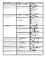
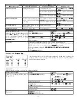
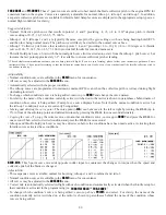
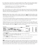
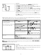
GOAL of EXAMPLE:
STEPS:
INPUTS:
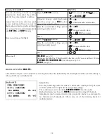
6HWXSDKHDGLQJKROG$9&6J\URZLWK
KHDGLQJKROG$9&6 VHWWLQJ LQ LGOHXSV
1 and 2 and normal mode setting in idle-
up3 and normal.
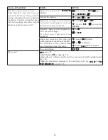
Open and activate the
GYRO SENSE
function.
for 1 second.
(If
BASIC
,
again.)
C
to
GYRO SENSE
.
Activate the function.
C
to
MIX
.
to
ACT
.
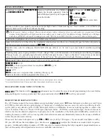
Optional: change gyro type to Heading-
hold (
GY
).
C
to
MODE
.
to
GY
.
Optional: change switch assignment.
Ex: select
Cond
.
C
to
SW
.
to
Cond
.
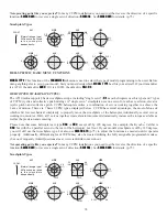
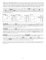
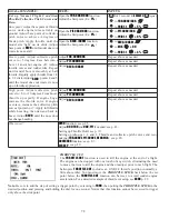
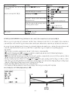
Adjust gyro rates as needed.
(Ex:
NORM
,
IDL3
to
NOR 50%
.
IDL1
and
2
to
AVC 50%
as starting points.)
C
to
NORM
.
to
NOR 50%
.
C
to
IDL1
.
to
AVC 50%
.
Repeat.
Close the function.
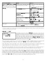
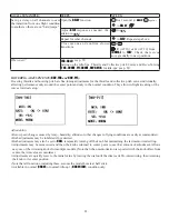
Where next?
GOVERNOR
: see p. 87.
D/R
,
EXP
: see p. 30.
DELAY
: see p. 82.
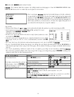
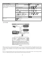
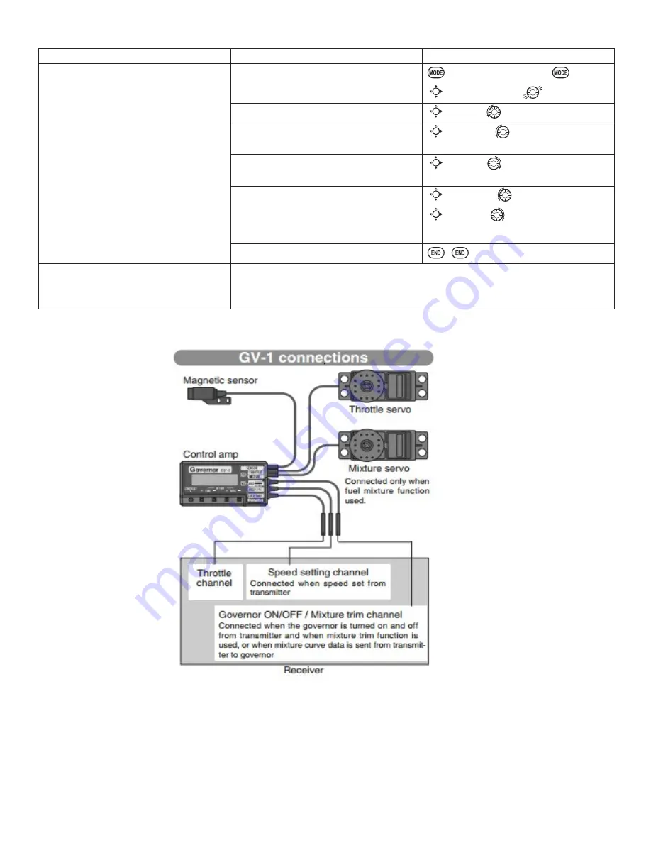
GOVERNORS:
What is a governor? A governor is made up of a set of sensors which read the RPM of the helicopter’s head, and a
control unit that automatically adjusts the throttle setting to maintain a constant head speed regardless of changes in pitch
of blades, weather conditions, etc. Governors are extremely popular in competition helicopters due to the consistency
provided.
How does it help in helicopter setup? The governor eliminates the need to spend large amounts of time setting up throttle
curves, as it automatically adjusts the engine’s RPM to maintain the desired head speed.

