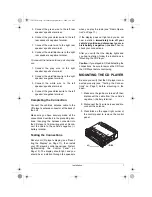
background image

5

Installation

MAKING THE 
CONNECTIONS

The supplied harness with the 14-pin con-
nector includes all the lead wires you need to
connect the CD player to ground, power, op-
tional components, and speakers.

Important: Do not cut these wires. If you cut
any wire, you cannot obtain a refund or ex-
change on this product. However, your Ra-
dioShack store will provide warranty service
if you cut a wire and find the product is defec-
tive.

You might need additional wire, depending
on your individual auto sound system, to
complete the connections. Your local Ra-
dioShack store carries a full line of wire and
wire management accessories.

Cautions:

• For added safety and to protect your CD

player, disconnect the cable from your
vehicle battery’s negative (–) terminal
before you begin.

• Be sure your speakers can handle 50

watts of power (25 watts per channel if
you are using one pair of speakers).
Each speaker must have an impedance
of at least 4 ohms. Your local
RadioShack store carries a full line of
speakers.

• You must connect the GROUND (–),

+12V TO IGNITION, and +12V TO BAT-
TERY wires first, then make all other
connections as described in the follow-
ing sections before you plug the harness
with the 14-pin connector into the CD
player. If you do not make connections
in the order shown, damage to the CD
player is possible if any wire connec-
tions are made incorrectly.

• You must connect a separate wire to

each speaker terminal as described in

the following procedure. Do not use a
common wire or chassis ground for any
speaker connection.

The CD player’s buzzer alarm sounds if you
make an incorrect connection that could
damage the circuit.

Using an Adapter Harness 

If you are replacing an existing CD player, or
if your vehicle has been factory-wired for
auto sound components, you might be able
to use an adapter harness to connect the
power and speakers. RadioShack sells
adapter harnesses for most vehicles.

Follow the directions that come with the
adapter harness to temporarily connect the
ground, power optional components and
speakers. Then go to “Completing the Con-
nection” on Page 7.

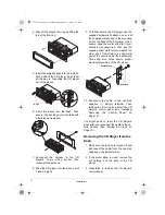
Connecting Ground, Power, and 
Optional Components

1. Disconnect the cable from your vehicle’s

negative (–) battery terminal.

2. Connect the black ground wire (with fil-

ter and fuse box) to a chassis ground,
such as a metal screw attached to a
metal part of the vehicle’s frame. Be
sure that the screw is not insulated from
the chassis by a plastic part.

3. Connect the red power wire (with in-line

fuse holder) to a point in your vehicle’s
fuse block that has power only when you
turn the vehicle’s key to either the
accessory (ACC) or the START position.
This prevents your vehicle’s battery from
being drained if you leave the CD player
on when you turn off the ignition.

4. Connect the yellow power/memory wire

(with filter and fuse box) to your vehicle
battery’s positive (+) terminal or to a

12-2158.fm  Page 5  Wednesday, September 13, 2000  1:50 PM

Содержание 12-2158

Страница 1: ...Owner s Manual Please read before using this equipment Flat Face Car CD Player with Signal Level Meter Display 12 2158 fm Page 1 Wednesday September 13 2000 1 50 PM...

Страница 2: ...Toyota Nissan and Suzuki Vehicles 9 Installing Removing the Control Panel 10 Operation 10 Setting the Clock 10 Adjusting the Sound 11 Resetting the Display 11 Radio Operation 11 CD Player Operation 12...

Страница 3: ...oise caused by your vehicle s electrical system Liquid Crystal Display With Clock shows the current operation of the CD and tuner with bar spectrum signal level display Buzzer Alarm alerts you when th...

Страница 4: ...This auto sound CD player system is a DIN E size unit that requires a 21 24 inch high by 71 24 inch wide by 71 220inch deep 57 184 190 mm mounting area Cautions Make sure your vehicle s mounting area...

Страница 5: ...u must connect a separate wire to each speaker terminal as described in the following procedure Do not use a common wire or chassis ground for any speaker connection The CD player s buzzer alarm sound...

Страница 6: ...the CD player works properly remove the CD player s control panel and disconnect your vehicle battery s negative cable the harness from the CD player s 14 pin wiring socket Then proceed with the insta...

Страница 7: ...nnections Reset your CD player s display see Reset ting the Display on Page 11 then install your CD player s control panel see Install ing Removing the Control Panel on Page 10 The display should ligh...

Страница 8: ...nting area Then use the supplied sheet metal screw to attach the other end of the strap to a solid metal part of the vehicle under the dashboard This strap also helps ensure proper electrical groundin...

Страница 9: ...san or S Suzuki located on both sides of the CD player to fasten the CD player to the factory radio mounting brackets supplied with your ve hicle 1 Use a Phillips screwdriver to loosen and remove the...

Страница 10: ...clean do not touch the connecting pins in the recess or on the back of the control panel Operation Caution Do not change your CD player s settings in heavy traffic or during hazardous driving conditi...

Страница 11: ...r appears 6 To increase bass output press LOUD LOUD appears To return bass output to normal press LOUD again and LOUD disappears To temporarily silence the CD player press MUTE MUTE appears To resume...

Страница 12: ...OAdcd appears then CdP CD play then TRACK 01 and the CD plays from Track 1 If a CD is already in the CD player simply press MODE to play the CD The CD player displays the number of the last track you...

Страница 13: ...ct the CD and check it for scratches and condensation see CD Care Tips on Page 14 Reload the CD and try again to play it or try a different CD If the CD player still does not operate properly take it...

Страница 14: ...If you park your vehicle in the sun tem peratures inside the vehicle can easily reach levels that could damage your CDs To prevent heat damage avoid leaving your CDs in your vehicle If a CD skips whe...

Страница 15: ...tion Ref 0 3 CD Used diameter 5 inch 120 mm Signal Format D A Conversion 1Bit Linear Transmission Bit Rate 1 4 Mbit Sec Sampling Frequency 8 Times Pick Up System Optical Pick Up Optical Source Laser N...

Страница 16: ...ations on how long an implied warranty lasts or the exclusion or limitation of incidental or consequential damages so the above limitations or exclusions may not apply to you In the event of a product...

Отзывы: