Installation Manual
Wall Hung Boiler with D.H.W. Storage Cylinder Low Nox – Cod. 99881NA – July 2001
17
BOILER MAINTENANCE
(carried out by qualified heating engineers)
Every 12 months, or more frequently if the quality and consumption of water
demand it, check the condition of the magnesium anode and replace it if signs of
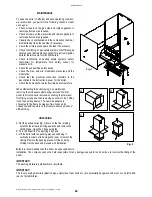
wear are evident. To check the condition of the anode 3 (see fig.1), open valve 4
on the top of the boiler, undoing the red knob in a clockwise direction. If water
seeps out of the valve this means the anode is worn and must be replaced. If on
the other hand there is no evidence of water leaking out, the anode can still be
used. After carrying out the operation described here, remember to tighten the
valve once more.
If the water pressure exceeds 6
bar, fit a 2 lt expansion tank to the boiler, proceeding as follows (see fig.1)
a. empty the water content of the boiler
b. undo the 1 / 2” cap (1) on top of the boiler;
c. fit the expansion tank 2;
d. fill the boiler once more.
LIMITER
The boiler is equipped with a variable flow limiter at the cold water inlet. The
flow limiter can be adjusted by turning the screw (see fig.3 pos.C) in order to
obtain the correct flow rate of domestic hot water for the specific boiler
output.
FLOWSWITCH
This device gives precedence to domestic hot water and is fitted to boilers
which supply instantaneous hot water (see fig. 2, item B fig. 3). It allows
conversion to hot water even with a minimum hot water demand (2
litres/min.), using an electromagnetic principle with electrical switching by
means of a relay. The device is made of non-toxic, corrosion-proof ZYTEL
101 L plastic material which has type approval with non-toxic characteristics
and is unaffected by hard water. In addition, a filter is fitted before the
flowswitch and at the cold water inlet which eliminates any water impurities.
These features guarantee that the flowswitch operation is highly efficient.
BY-PASS
All boilers are fitted with a by-pass. This element is essential in the following
cases:
#
if a two-way zone valve is installed
#
if thermostat valves are installed in the radiators.
To adjust the by-pass proceed as follows (see fig. 3 pos.A): fit the screwdriver
to the plastic screw of the by-pass, bearing in mind that when the slot of the
screw is horizontal the by-pass is totally open, allowing all the water to pass,
while when it is vertical the by-pass is totally closed. For partial by-pass flows,
use the adjuster screw.
D.H.W. CIRCULATING LOOP
It is possible to make a d.h.w. circulating loop. Please proceed as follows:
unscrew CAP A on the cylinder top,, insert a stainless steel PIPE B (supplied
by the manufacturer with a kit) into the ½” union and connect here the
circulating loop pipe C. If necessary, fit an expansion vessel (as shown in fig.1)
inserting a “T” connection between the circulating loop pipe and the cylinder ½”
union.
A
C
B
1
3
2
4
Flowswitch
C
B
A
Fig. 1
Fig. 2
Fig. 4
Fig. 3
Содержание RMA
Страница 2: ......


