Radiant, Inc.
8
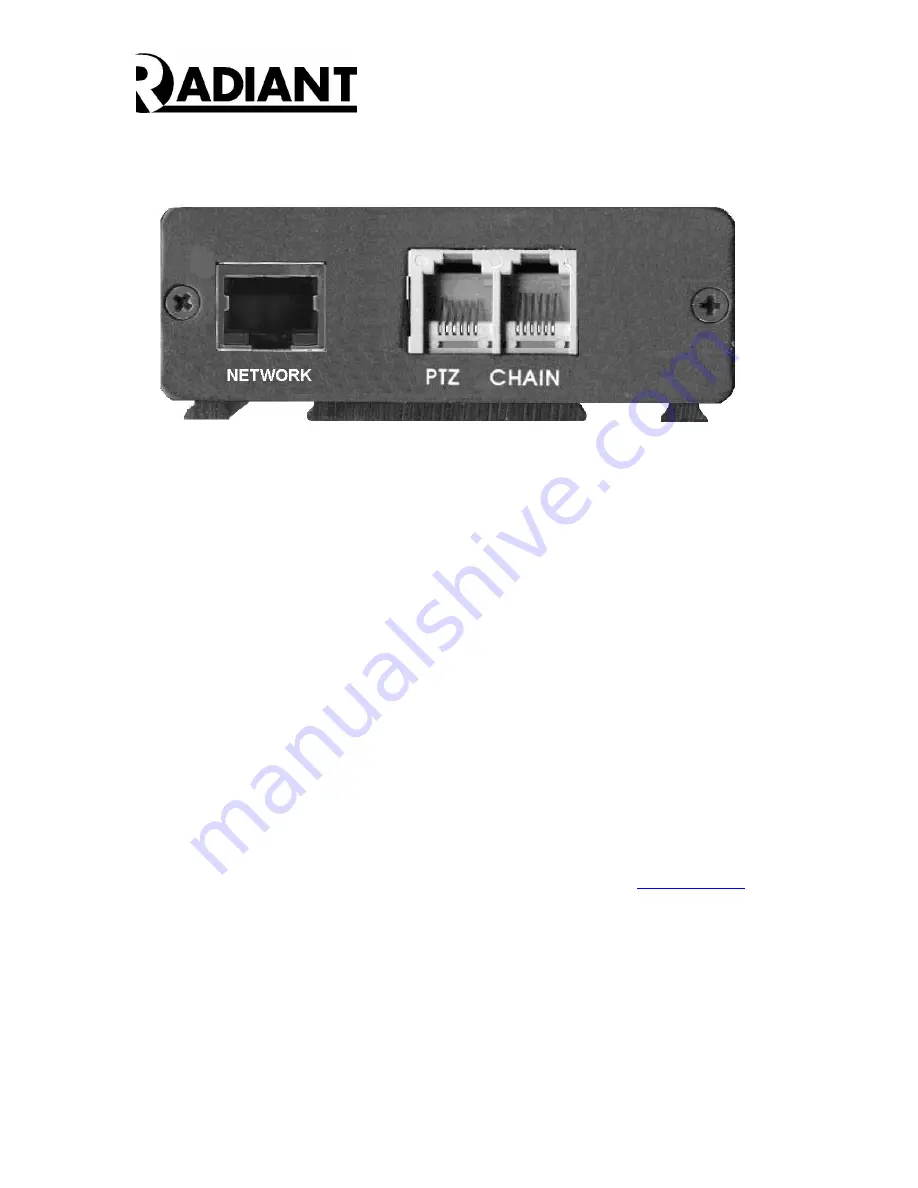
Figure 5 – DVMD1-X Rev B Rear Panel
•
Step Five:
The Unit Address is internally set to FF0 for the DVMD1-X so there is no rotary switch
The RS485 CHAIN is internally terminated so there is no TERM switch on the DVMD-X.
All other DVMD1-X termination switches should NOT be terminated. A six-conductor
phone wire may be used to connect from the CHAIN output of the first unit (FF0) to the
next unit.
Power up the camera, the CCTV monitor and the DVMDs. You should get a video
picture with overlay on the monitor. If you do not get a picture on the monitor re-check
Steps 1 – 6 above. If you do get a video image on the monitor, proceed with loading the
User Interface Software as described in the User Interface – Manager Tools Window
paragraph below.
If the power to the DVMD is off, the video from the camera is connected directly to the
CCTV monitor through an internal video bypass relay. In the power off state, no DVMD
functions occur, and no overlay is generated.
User Interface – Manager
You may download the most recent firmware and software at
www.dvmd.com
. The
ManagerNET.exe
program provides the user interface to the DVMD. Please refer to the
DVMD Software User’s Manual for further information.
XPORT User Manual
Please also refer to the XPORT User Manual to change the IP address and Local Port
number for each DVMD1-X.


