Radiant, Inc.
7
CONNECTION INSTRUCTIONS
Connecting the DVMD to a camera and computer is a simple process. The connections should
be accomplished in the sequence outlined below.
•
Step One:
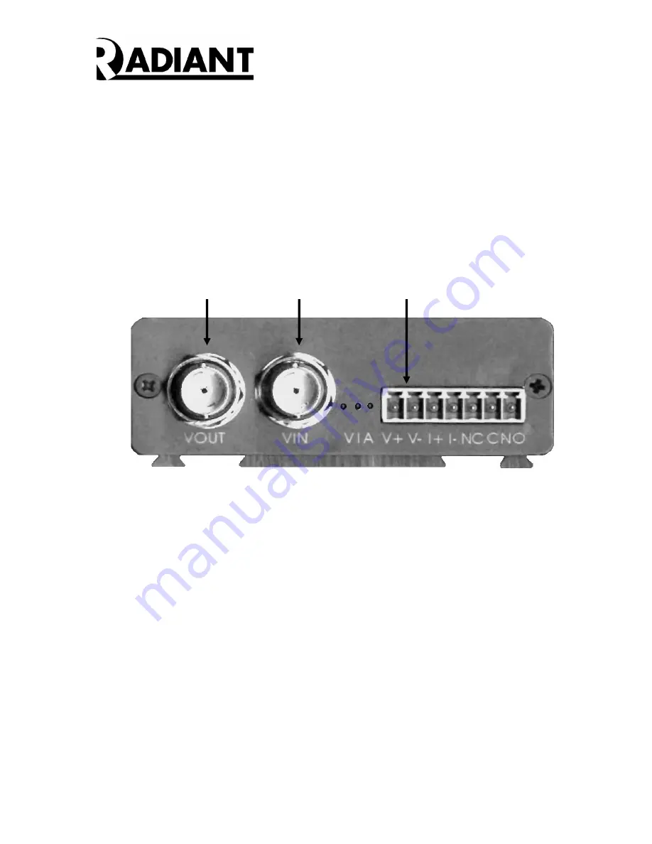
Connect the +12 VDC Power Supply by attaching the positive supply output to V+ and
ground to V-. These screw connectors are located on the Front Panel of the DVMD-X
(See Figure 4).
Figure 4 – DVMD Front Panel
•
Step Two:
Connect a 75 ohm Coaxial Cable from the VOUT BNC connector located on the DVMD
Front Panel (See Figure 3) to the Video In port on a CCTV Monitor.
•
Step Three:
Connect a second 75 ohm Coaxial Cable from the VIN BNC connector on the DVMD
Front Panel (See Figure 3) to the Video Out port on a camera.
•
Step Four:
Connect the NETWORK connector (See Figure 5) to a HUB/Router with a CAT5 Cable,
or to the NIC card in the PC using a crossover cable. The Green LED should light up
when the network connection is established.
Step 1
V+ Connection
Step 2
Video Out
Step 3
Video In


