Radial Engineering Ltd.
PZ-DI™ User Guide
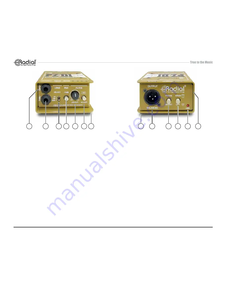
INPUT PANEL
1. INPUT: ¼” hi-Z input used to connect the instrument to the PZ-DI.
2. THRU: ¼” throughput used to feed an on-stage instrument amplifier.
3. LOAD: 3-position switch lets you adjust the input impedance to
optimize the load for the type of pickup being used. Set to 220k
ohm for magnetic pickups, 10 meg-ohm for piezo transducers and
1 meg-ohm to replicate traditional DIs.
4. PAD: Reduces the input sensitivity by -15dB enabling the PZ-DI
to be used with high output instruments such as active basses or
keyboards.
5. LO-CUT: Variable high-pass filter is used to remove unwanted
resonance and size the instrument to suit. Variable from 5Hz to
500Hz.
6. HI-CUT: Used to warm up the sound of active instruments that often
contain excessive high frequencies.
7. BOOK-END DESIGN: Creates protective zone around con
-
nectors, switches and potentiometers to prevent damage.
OUTPUT PANEL
8. NO SLIP PAD: Provides electrical and mechanical isolation while
keeping the PZ-DI from sliding around on busy stages.
9. XLR OUT: Balanced low impedance output used to connect the
PZ-DI to the mixing console. Allows long cable runs in excess of
100 meters (300 feet) without noise.
10. PHASE: 180° polarity reverse toggles pin-2 and pin-3 at the XLR
output. Used to tame acoustic hot spots on stage and help reduce
resonant feedback.
11. LIFT: Ground lift switch disconnects the ground from the audio
signal path and helps eliminate hum and buzz caused by ground
loops.
12. 48V: Provides visual status of 48V phantom power. When the LED
is on, the PZ-DI is being fed 48 volts from the console.
13. THRU BUFFER ON: Buffers the signal before it is sent to the thru-
put connector for use with piezo transducers or when using longer
cable runs.
1
2
3 4
5
6 7
8
9
10 11
13
12
2
Содержание PZ-DI
Страница 2: ......


