VB2SX20SPS User Guide
Page 21 of 24
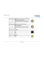
Connector 5
– CAN (First CAN Bus Connector, Serial Connection to GPS Engine)
Pin
I/O
Function
1
O
RS232 Tx GPS (Tx Data from GPS engine)
2
I
RS232 Rx GPS (Rx Data to GPS engine)
3
I/O
CAN High (Also direct connection to Connector 6 CAN High)
4
I/O
CAN Low (Also direct connection to Connector 6 CAN Low)
5
I/O
Power +
Chassis
I
Ground
Connector 6
– SERIAL (Setup / Upgrade, Second CAN Bus Connector)
Pin
I/O
Function
1
O
RS232 Tx Serial Data transmit
2
I
RS232 Rx Serial Data receive
3
I/O
CAN High (Also direct connection to Connector 5 CAN High)
4
I/O
CAN Low (Also direct connection to Connector 5 CAN Low)
5
I/O
Power +
Chassis
I
Ground
Connector 7
– USB (Setup / Upgrade)
Pin
I/O
Function
1
2
I/O
USB
–
3
I/O
USB+
4
I/O
Ground
Chassis
I
Ground
Connector 8
– ANT (GPS Antenna)
Pin
I/O
Function
1
I
Signal
Chassis
I
Ground

