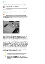
background image

3.

Note that there is a danger of crushing and cutting injuries occurring in the
area of the three-point linkage.
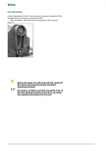
4.

DO NOT pass between the tractor and implement once the three-point
linkage has been connected to the vehicle mounted controls.
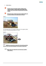
5.

Always ensure, when the implement is raised for towing, that the tractor’s
three-point linkage is adequately secured at the sides.

6.

Before driving the outfit on the road, ensure that the operating lever is
secured to stop the implement being lowered by accident.
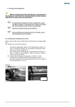
7.

Hitch up and connect implements in accordance with regulations. Check
the trailer braking system for correct functioning. Observe the
manufacturer’s instructions.

8.

Working implements should only be towed and operated using tractors
designed for the purpose,

Содержание 230

Страница 1: ...Flail Mower Chopper 230 250 280 Operating Instructions Serial No Order No 9900 01 40GB01...

Страница 2: ...machine Carefully read through the operating instructions BEFORE starting up the machine for the first time Please ensure that this manual is handed over to the new owner if the machine is sold or oth...

Страница 3: ...original spare parts If the user has failed to observe the operating instructions contained in this manual If the permitted performance limits have been exceeded see table 1 in the section entitled T...

Страница 4: ...Options Depending on the operating conditions the following cutting implements can be used Optional Y blades for stalks trunks of up to 3 cm in diameter Standard bootee flails for stalks trunks of up...

Страница 5: ...o the implement contain important instructions on how to operate it safely Prevent danger by observing them at all times 3 Be sure to observe all relevant traffic laws when using public roads 4 Famili...

Страница 6: ...ree point hydraulic linkage to stop the implement rocking back and forth 18 Ensure that all safety devices are attached and in full working order BEFORE you operate the implement 19 DO NOT remain with...

Страница 7: ...aised for towing that the tractor s three point linkage is adequately secured at the sides 6 Before driving the outfit on the road ensure that the operating lever is secured to stop the implement bein...

Страница 8: ...is normal for the power take off shaft see table of settings 8 Gentle handling of the coupling elements will help ensure a long service life for both the tractor and the mulching implement 9 Clear th...

Страница 9: ...t possible injury Always use appropriate detection equipment when checking for leaks 6 Pressurised fluids hydraulic oil are apt to escape without warning possibly resulting in skin penetration and ser...

Страница 10: ...regular intervals for correct tightness and retighten as required 3 Insert adequate props and or axle stands before working on the raised implement 4 Dispose of waste oil lubricants and filters correc...

Страница 11: ...es fig 4 are available for lighter mulching tasks stalks trunks of up to 3 cm The rotor shaft turns in the opposite direction to the direction of travel at a rate of 2 243 rpm The implement is operate...

Страница 12: ...at the implement is in full working order that all safety devices are in their correct positions that all cutting tool attachments fitted to the rotor shaft are in full working order that grease has b...

Страница 13: ...actor As the adjustment procedure only applies to this type of tractor the procedure must be checked and if necessary repeated whenever a different tractor is used Whenever you fit a new drive shaft e...

Страница 14: ...he implement in its horizontal position 5 4 Tractor stability Depending on the size of the tractor the load on its front axle will be relieved to some degree or other as the implement is raised Ensure...

Страница 15: ...ff the ground fig 11 and that it runs on its roller The roller must be adjusted if the cutting height is to be increased Fig 12 Fig 11 Fig 12 Neither the tool attachments nor slides must not touch the...

Страница 16: ...ee description of V belt tension on page 28 of this manual Fig 14 Always disengage the power take off shaft switch off the engine and remove the ignition key before tensioning the V belt The V belt is...

Страница 17: ...haft turning speed of the implement The limit is 540 rpm the ideal speed 1 000 rpm Fig 15 The operating speed of the implement depends on the vegetable matter being cut The ideal operating speed is 3...

Страница 18: ...inimum Disengage the power take off shaft for towing When uncoupling the implement observe the safety precautions listed on page 10 under Coupling Always park the implement on a dry and even surface a...

Страница 19: ...refitted 9 1 Checking the transmission oil level Always use the same type of lubricant for transmission oil changes SAE 90 To change the oil proceed as follows Unscrew the plug at the bottom of the tr...

Страница 20: ...ment Running roller bearing left fig 20 2 1 x Running roller bearing right fig 21 3 1 x Rotor shaft bearing left fig 20 1 1 x Rotor shaft bearing right fig 21 4 1 x Fig 20 Fig 21 Always wear protectiv...

Страница 21: ...the tension then retighten the locknut Refit the V belt guard Fig 22 Fig 23 Fig 24 The V belts are normally correctly tensioned if a force of 100 N 10 kg weight results in around 1 5 cm of play when a...

Страница 22: ...es that may be wrapped around the rotor shaft wire etc Check the hook trestle and housing for signs of cracks Reapply grease as required at each lubrication point page 27 3 After every 100 hours of op...

Страница 23: ...Check coupling alignment Cutting tool attachments clogged due to excessive driving speed Reduce driving speed Noise Loose screws and bolts Retighten Machine damage Contact service workshop Out of true...

Отзывы: