Hardware Connections
Step 1 — Prepare the Interface Board
Insert a short plastic standoff supplied from the
Development Kit in one of the corner holes from
the bottom of the Interface Board, then secure it
with a long plastic standoff from above as shown
in Figure 1. Repeat this step so that plastic
standoffs/ connectors are in place at
all four
positions.
Step 2 — Install Module on Interface
Board
Position the RCM5700/6700 module with the
Figure 1. Insert Standoffs/Connectors
edge connectors facing the mini PCI Express socket J1A at an angle as shown in Figure 2 below.
Insert the edge connectors into the mini PCI Express socket J1A, then press down on the opposite
edge of the RCM5700/6700 module to snap it into place in holder J1B.
Figure 2. Install the RCM5700/6700 Module on the Interface Board
Should you need to remove the RCM5700/6700 module, use two fingers to hold back the spring clip
at J1B from the two RCM5700/6700 corners, lift up the edge of the RCM5700/6700 above J1B, then
pull the RCM5700/6700 away to remove the edge connectors from the mini PCI Express socket.
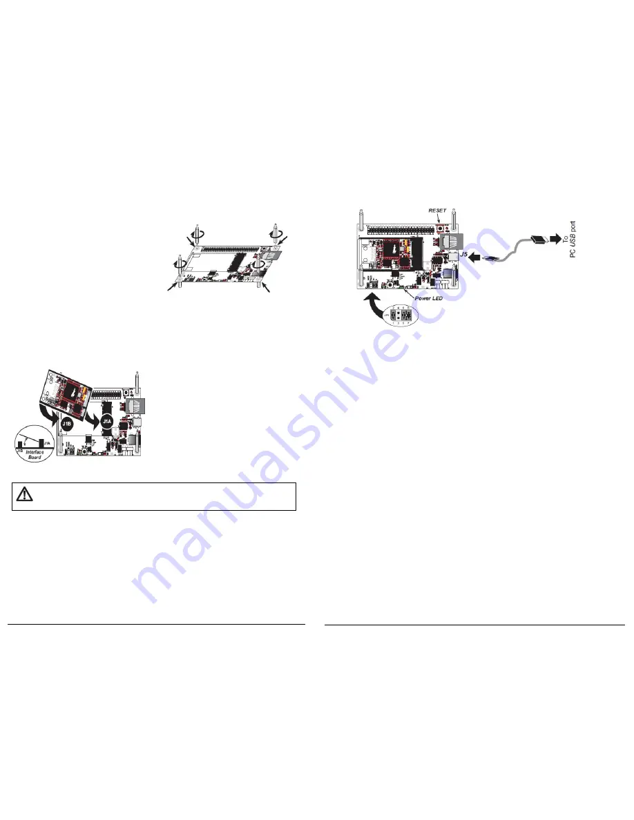
Step 3 — Connect USB Cable
The USB cable connects the RCM5700/6700 to the PC running Dynamic C to download programs
and to monitor the RCM5700/6700 module during debugging. It also supplies power to the
Interface Board and the RCM5700/6700 via the USB interface.
Connect the USB cable between USB connector J5 on the Interface Board and your PC as shown
in Figure 3. Note that the USB cable connectors are different at either end, so there is only one
way to connect them between the PC and the Interface Board.
2
Figure 3. Connect USB Cable
Your PC should recognize the new USB hardware, and the LEDs next to the USB connector on the
Interface Board will flash — if you get an error message, you will have to install USB drivers. Drivers
for Windows XP are available in the Dynamic C
Drivers\Rabbit USB Programming
Cable\WinXP_2K
folder — double-click
DPInst.exe
to install the USB drivers. Drivers for
other operating systems are available online at
www.ftdichip.com/Drivers/VCP.htm
.
The green power LED on the Interface Board should light up when you connect the USB cable. The
MiniCore and the Interface Board are now ready to be used.
NOTE:
A
RESET
button is provided on the Interface Board above the Ethernet jack to allow a
hardware reset without disconnecting power.
NOTE:
Pins 1–2 on header JP1 on the Interface Board must be jumpered to download and debug
applications and sample programs with Dynamic C running. Pins 1–2 should be left unjumpered
to
run
an program already loaded in flash memory.
CAUTION:
Do not jumper pins 1–3 on header JP1 on the Interface Board.
NOTE:
You must cycle the main power on/off after you install or replace a backup battery to
minimize current draw from the battery.
Run a Sample Program
Once the RCM5700/6700 is connected as described above, start Dynamic C by double-clicking on
the Dynamic C icon on your desktop or in your
Start
menu. Select
Store Program in Flash
on the
“Compiler” tab in the Dynamic C
Options > Project Options
menu. Then click on the “Commu-
nications” tab and verify that
Use USB to Serial Converter
is selected to support the USB cable.
Click
OK
.
You may have to select the COM port assigned to the USB cable on your PC. In Dynamic C,
select
Options > Project Options
, then select this COM port on the “Communications” tab,
then click
OK
.
3
CAUTION:
Remove power before attempting to insert or remove the RCM5700/6700
in the mini PCI Express socket.