112
Rabbit 2000 Microprocessor
11.1 Timer A
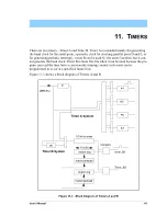
Timer A consists of five separate countdown timers—A1 and A4–A7—as shown in
Figure 11-1.
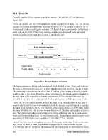
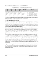
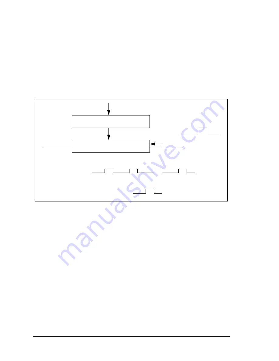
Timers A1 and A4–A7 are 8-bit countdown registers as shown in Figure 11-2. The reload
register can contain any number in the range from 0 to 255. The counter divides by (n+1).
For example, if the reload register contains 127, then 128 pulses enter on the left before a
pulse exits on the right. If the reload register contains zero, then each pulse on the left
results in a pulse on the right, that is, there is division by one.
Figure 11-2. Reload Register Operation
The timer systems are driven by the peripheral clock divided by two. This clock is always
the same as the processor clock, or it is faster than the processor clock by a factor of eight.
The output pulses are always one clock long. Clocking of the counters takes place on the
negative edge of this pulse. When the counter reaches zero, the reload register is loaded on
the next input pulse instead of a count being performed. The reload registers may be
reloaded at any time since the peripheral clock is synchronous with the processor clock.
Timers A4, A5, A6 and A7 always provide the baud clock for serial ports A, B, C and D
respectively. Except for very low baud rates, clock A1 does not need to be used to prescale
the input clock for timers A4–A7. For example, if the system clock is 11.0592 MHz, and if
the timer A4 divides by 144, an asynchronous baud rate of 2400 bps can be achieved in one
step. The clock input to the serial port must be 16 times the baud rate for asynchronous
mode and 8 times the baud rate for synchronous mode. The maximum asynchronous baud
rate with a 11.0592 MHz clock would be (11,059,200/(2*16) = 345,600.
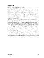
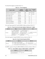
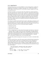
Each of the five countdown registers in timer A can cause an interrupt. There is one inter-
rupt vector for timer A and a common interrupt priority. A common status register
(TACSR) has a bit for each timer that indicates if the output pulse for that timer has taken
8-bit down counter
8-bit reload register
Clock in
pulse on zero count out
load
Input Clock
Count value
2
1
0
N
N - 1
1
0
2
Output pulse
Содержание 2000
Страница 1: ...Rabbit 2000 Microprocessor User s Manual 019 0069 041018 M...
Страница 12: ...6 Rabbit 2000 Microprocessor...
Страница 46: ...40 Rabbit 2000 Microprocessor...
Страница 54: ...48 Rabbit 2000 Microprocessor...
Страница 76: ...70 Rabbit 2000 Microprocessor...
Страница 96: ...90 Rabbit 2000 Microprocessor...
Страница 142: ...136 Rabbit 2000 Microprocessor...
Страница 154: ...148 Rabbit 2000 Microprocessor...
Страница 170: ...164 Rabbit 2000 Microprocessor...
Страница 174: ...168 Rabbit 2000 Microprocessor...
Страница 180: ...174 Rabbit 2000 Microprocessor...
Страница 202: ...196 Rabbit 2000 Microprocessor...
Страница 206: ...200 Rabbit 2000 Microprocessor...
Страница 226: ......
Страница 230: ...224 Rabbit 2000 Microprocessor...

