manualshive.com logo in svg
background image

Rabbit 2000

®

 Microprocessor

User’s Manual

019–0069

041018–M

®

Содержание 2000

Страница 1: ...Rabbit 2000 Microprocessor User s Manual 019 0069 041018 M...

Страница 2: ...00 Microprocessor User s Manual Part Number 019 0069 041018 M Printed in U S A 1999 2004 Rabbit Semiconductor All rights reserved Rabbit Semiconductor reserves the right to make changes and improvemen...

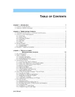
Страница 3: ...iderations 21 3 3 Instruction Set Outline 22 3 3 1 Load Immediate Data To a Register 23 3 3 2 Load or Store Data from or to a Constant Address 23 3 3 3 Load or Store Data Using an Index Register 24 3...

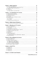
Страница 4: ...Functions 71 7 1 Processor Identification 71 7 2 Rabbit Oscillators and Clocks 72 7 3 Clock Doubler 74 7 4 Controlling Power Consumption 76 7 5 Output Pins CLK STATUS WDTOUT BUFEN 77 7 6 Time Date Clo...

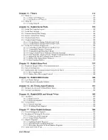
Страница 5: ...Slave Protocol 135 12 7 8 Data Framing Modbus 135 Chapter 13 Rabbit Slave Port 137 13 1 Hardware Design of Slave Port Interconnection 143 13 2 Slave Port Registers 143 13 3 Applications and Communicat...

Страница 6: ...ifferences Rabbit vs Z80 Z180 Instructions 187 Chapter 20 Instructions in Alphabetical Order With Binary Encoding 189 Appendix A 197 A 1 The Rabbit Programming Port 197 A 2 Use of the Programming Port...

Страница 7: ...llows maximum utilization of the mem ory bandwidth The Rabbit races through instructions Traditional microprocessor hardware and software development is simplified for Rabbit users In circuit emulator...

Страница 8: ...nes are timer syn chronized which permits precisely timed edges and pulses to be generated under com bined hardware and software control There are four serial ports All four serial ports can operate a...

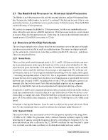
Страница 9: ...per second This is a powerful alternative to sleep modes of operation used by other processors The current is approximately 65 mA at 25 MHz and 5 V The current is pro portional to voltage and clock s...

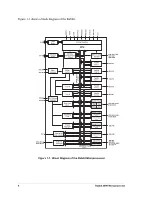
Страница 10: ...strap Real Time Clock Serial Port B Asynchronous Serial Synchronous Serial 32 768 kHz Oscillator Watchdog Timer Asynchronous Serial Serial Port C Periodic Interrupts Asynchronous Serial Serial Port D...

Страница 11: ...beit at 32 kHz The Rabbit may be used to create an intelligent peripheral or a slave processor For example protocol stacks can be off loaded to a Rabbit slave The master can be any processor The Rabbi...

Страница 12: ...6 Rabbit 2000 Microprocessor...

Страница 13: ...embedded systems The Rabbit has no support for DMA direct memory access because most of the uses for which DMA is traditionally used do not apply to embedded systems or they can be accomplished better...

Страница 14: ...essage is also supported The software can tell when the last byte of a message has finished transmitting from the output shift register correcting an important defect of the Z180 This is important for...

Страница 15: ...erial data or chip select strobes Parallel ports D and E have the capability of timer synchronized outputs The out put registers are cascaded Figure 2 1 Cascaded Output Registers for Parallel Ports D...

Страница 16: ...s to one of the registers carrying data bits outward an attention line is enabled so that the master can detect the data change and be interrupted if desired One line tells the master that the slave h...

Страница 17: ...nt in the future This pulse can be used to clock the timer synchronized parallel port output registers as well as cause an interrupt Timer B is convenient for creating an event at a precise time in th...

Страница 18: ...ill not be nec essary in most cases Rabbit Semiconductor supports the use of the standard programming port and the standard programming cable as a diagnostic and setup port to diagnosis problems or se...

Страница 19: ...ition in the instruction set as the Z80 R register but its function is to point to an interrupt vector table for internally generated interrupts Figure 3 1 Rabbit Registers A F H L D E B C IX IY SP PC...

Страница 20: ...ns The addressing range is expanded by means of the memory mapping hardware see Memory Mapping on page 15 and by special instructions For most embedded applications 64K of data mem ory as opposed to c...

Страница 21: ...s 20 bit addresses The processor except for certain LDP instructions sees only a 16 bit address space That is it sees 65536 distinctly addressable bytes that its instructions can manipulate Three segm...

Страница 22: ...star tup code as well as other code that may happen to be stored there The data segment usage varies depending on the overall strategy for setting up memory It may be an extension of 10000 E000 D000...

Страница 23: ...orrespond to the normal control lines found on static mem ory chips chip select or CS output enable or OE and write enable or WE In order to generate these memory control signals the 20 bit address sp...

Страница 24: ...nstructions mod ify both the program counter PC and the XPC register causing the XPC window to point to a different part of memory where the target of the long jump call or return is located The XPC s...

Страница 25: ...of root code This amount of data space is more than sufficient for most embedded applica tions One approach to getting more data space is to place data in RAM or in flash memory that is not mapped int...

Страница 26: ...the stack segment Another possibility is to have a data structure and a stack located together in the stack segment and to use a different stack segment for different tasks each task having its own d...

Страница 27: ...ay require large data arrays or tables that will require additional data memory For this purpose Dynamic C supports a type of extended data memory that allows the use of additional data memory even ex...

Страница 28: ...cks for each byte of the op code and for each data byte read Three clocks are needed for each data byte written One additional clock is required if a memory address needs to be computed or an index re...

Страница 29: ...Immediate Data To a Register A constant that follows the op code in the instruction stream can generally be loaded to any register except PC AF IP and F Load to the PC is a jump instruction This inclu...

Страница 30: ...gisters above or an immediate data byte LD HL g not a legal instruction LD r IX d r is any of 7 registers d is 128 to 127 offset LD g IX d same but alternate destination LD IX d r r is any of 7 regist...

Страница 31: ...L DE BC 2 bytes 4 clocks LD dd DE LD IX HL LD IY HL LD HL IY LD HL IX LD SP HL 1 byte 2 clocks LD SP IX LD SP IY Other 16 bit register moves can be constructed by using 2 byte moves 3 3 5 Register Exc...

Страница 32: ...re ww is HL DE BC SP ADC HL ww ADD and ADD carry SBC HL ww sub and sub carry INC ww increment the register without affecting flags In the above op codes IX or IY can be substituted for HL The ADD and...

Страница 33: ...L SBC HL HL sets HL 0 if C 0 sets HL 0x0ffff if C 1 BOOL HL HL 1 if C was set otherwise HL 0 convert not carry bit into boolean variable in HL SBC HL HL HL 0 if C 0 else HL ffff if C 1 INC HL HL 1 if...

Страница 34: ...LD DE n2 LD A b save sign of BC MUL form product in HL BC OR a test sign of BC multiplier JR p x1 if plus continue ADD HL DE adjust for negative sign in BC x1 RL DE test sign of DE JR nc x2 if not ne...

Страница 35: ...ke place instead of a mem ory access operation The problem was corrected in revisions A C of the Rabbit 2000 Refer to Appendix B for further information to determine which version of the Rabbit 2000 c...

Страница 36: ...list Rabbit users are unlikely to encounter this problem because the sequence of instructions that exhibit the bug is never generated by the Dynamic C compiler or in any of the stan dard libraries Be...

Страница 37: ...XX 2 EX DE HL 2 Move between IX IY and DE DE IX IY DE DE IX IY IX IX DE EX DE HL LD HL IX IY LD IX IY HL EX DE HL 8 clocks total DE IX IY EX DE HL LD IX IY HL EX DE HL 8 clocks total 3 4 3 Manipulatio...

Страница 38: ...in DE these operations can be performed as follows assuming that the object is to set HL to 1 or 0 depending on whether the compare is true or false compute HL DE unsigned integers EX DE HL uncomment...

Страница 39: ...0 always false LD DE 65536 B ADD HL DE not carry if HL B SBC HL HL 1 if carry else 0 INC HL 14 clocks 0 if carry else 1 if no carry HL B B is constant not zero LD DE 65535 B ADD HL DE C if HL B CCF C...

Страница 40: ...l true if HL 5 else false Figure 3 7 Mapping Signed Integers to Unsigned Integers by Inverting Bit 15 3 4 5 Atomic Moves from Memory to I O Space To avoid disabling interrupts while copying a shadow r...

Страница 41: ...ne address for RST interrupts Since interrupt routines do not affect the XPC interrupt routines must be located in the root code space However they can jump to the extended code space after saving the...

Страница 42: ...evel 1 except in carefully considered situations The effect of the processor priority on interrupts is shown in Table 3 1 The priority of the interrupt is usually established by bits in an I O control...

Страница 43: ...nes for the separate devices before they are or ed together The interrupt dis patcher calls the interrupt routines for all devices requesting interrupts in priority order so that all interrupts are se...

Страница 44: ...does not have an embed ded critical section If this code is nested there is the danger of overflowing the IP register A different version that can be nested is the following PUSH IP IPSET 1 save prev...

Страница 45: ...HL In this case A has the new XPC and HL has the new PC This code should normally be executed in the root segment so as not to pull the memory out from under the JP HL instruction A call to a computed...

Страница 46: ...40 Rabbit 2000 Microprocessor...

Страница 47: ...e priority of the interrupt and the amount of time that other interrupt routines of the same or higher priority inhibit interrupts The first instruc tion of the interrupt routine will start executing...

Страница 48: ...register is loaded with the contents of the next match register when a pulse is gener ated This allows events to be very close together one count of Timer B Timer B can be clocked by sysclk 2 divided...

Страница 49: ...5 get current output ld e a 2 ld a maskor 9 or a e 2 ioi ld port a 13 store in port inc hl 2 point to next ld a hl 5 check for end of array or a a 2 jr nz step2 2 ld hl beginptr 11 reset hl to start...

Страница 50: ...lel port D outputs can be individually programmed to be open drain This is use ful for scanning a switch matrix as shown in Figure 4 2 A row is driven low then the col umns are scanned for a low input...

Страница 51: ...ther memory or to internal I O space The high bit of the address is set to specify the I O space and thus writes are limited to the first 32K of either space The cold boot is terminated by a store to...

Страница 52: ...aster also can do a write to the status register which is used as a signaling device and does not actually write to the status register The three registers that the master can write appear as read reg...

Страница 53: ...upt driven trans fer will be on the order of 100 clocks per byte transferred assuming a 20 instruction inter rupt routine To keep the interrupt routine to 20 instructions the interrupt routine needs t...

Страница 54: ...48 Rabbit 2000 Microprocessor...

Страница 55: ...B PC6 TXA VDD VSS PC7 RXA CLK VSS VDD CS2 CS1 OE0 A10 CS0 D7 D6 D5 D4 D3 D2 D1 D0 A0 A1 A2 A3 SCS I7 PE7 I6 PE6 INT1B I5 PE5 INT0B I4 PE4 I3 PE3 I2 PE2 VSS VDD INT1A I1 PE1 INT0A I0 PE0 IORD IOWR PD0...

Страница 56: ...tered land pattern for the Rabbit 2000 chip as developed by the Surface Mount Land Patterns Committee and specified in IPC SM 782A Surface Mount Design and Land Pattern Standard IPC Northbrook IL 1999...

Страница 57: ...18 85 mm 23 0 mm 1 71 mm JT 0 27 0 53 mm Toe Fillet JH 0 22 0 55 mm Heel Fillet JS 0 0 122 mm Side Fillet TOLERANCE AND SOLDER JOINT ANALYSIS Zmax 18 71 or 24 71 mm Gmin 15 29 or 21 29 mm X 0 44 mm Wm...

Страница 58: ...the crystal should be short and shielded from crosstalk If an external clock is used this pin should be driven by the external clock 40 XTALA2 Output Quartz crystal for 32 kHz crystal oscillator Do n...

Страница 59: ...ough a controller that may have a slow propagation time 5 CS2 Output Memory Chip Select 2 connect to static memory chip Use this chip select last 4 Output Enables OE0 Output Memory Output Enable 0 con...

Страница 60: ...e clock for the clocked serial ports On reset the outputs are set to zero If the slave port is enabled the following alternate assignments apply PB7 SLAVEATTN slave requests attention PB5 PB4 address...

Страница 61: ...n external I O cycle to 1 8th of the 64K external I O space Each strobe can be programmed to be a chip select a write strobe a read strobe or a combined read and write strobe Any port bit used as an I...

Страница 62: ...are alternate pin assignments for parallel port D PD4 PD7 43 46 Slave Port SD0 SD7 Bidirectional Slave port data bus An alternate assignment for parallel port A 81 88 SLAVEATT N Output SLAVEATTN Slave...

Страница 63: ...is set up as input for parallel port E The value of the pin may also be read via the parallel port Uses bits 0 4 of the parallel port If parallel port is set up as output the parallel port output may...

Страница 64: ...ually accessed Output enable and write enable are always delayed by one clock from the time the final stable address and chip select are enabled Normally the false memory access attempts to start anot...

Страница 65: ...boot mode control 1 bit input after boot complete CLK 1 1 Peripheral clock 2 Peripheral clock 2 Programmable output port high low WDTOUT 34 Outputs 30 5 s pulse on watchdog timeout processor is also r...

Страница 66: ...2 58 TXC PC1 59 RXD PC0 60 TXD PD7 43 ARXA PD6 44 ATXA PD5 45 ARXB PD4 46 ATXB PD3 47 PD2 48 PD1 49 PD0 50 PE7 21 I7 programmable I O strobe SCS slave chip select PE6 22 I6 PE5 23 I5 INT1 input PE4 24...

Страница 67: ...d periods may affect the reliability of the Rabbit 2000 chip Table 5 3 Rabbit 2000 Absolute Maximum Ratings Symbol Parameter Maximum Rating TA Operating Temperature 55 C to 85 C TS Storage Temperature...

Страница 68: ...ns Min Typ Max Units IIH Input Leakage High VIN VDD VDD 5 5 V 10 A IIL Input Leakage Low no pull up VIN VSS VDD 5 5 V 10 A IOZ Output Leakage no pull up VIN VDD or VSS VDD 5 5 V 10 10 A VIL CMOS Input...

Страница 69: ...Min Typ Max Unit s IIH Input Leakage High VIN VDD VDD 3 6V 5 A IIL Input Leakage Low no pull up VIN VSS VDD 3 6V 5 A IOZ Output Leakage no pull up VIN VDD or VSS VDD 3 6V 5 5 A VIL CMOS Input Low Volt...

Страница 70: ...ted to take into consideration the current demands made my AC switching out puts capacitive loading on switching outputs and switching voltage The current ascribed to AC switching is the average curre...

Страница 71: ...Registers Register Name Mnemonic I O Address R W Reset Data Segment Register data segment memory pointer locates data segment in physical memory DATASEG Z180 BBR 0x12 R W 00000000 Segment Size Registe...

Страница 72: ...CR 0x99 W xx000000 Memory Bank 0 Control Register Rev A C MB0CR 0x14 W 00001000 Memory Bank 0 Control Register original chip MB0CR 0x14 W 00000000 Memory Bank 1 Control Register MB1CR 0x15 W xxxxxxxx...

Страница 73: ...Register PEB1R 0x79 W xxxxxxxx Port E Bit 2 Register PEB2R 0x7A W xxxxxxxx Port E Bit 3 Register PEB3R 0x7B W xxxxxxxx Port E Bit 4 Register PEB4R 0x7C W xxxxxxxx Port E Bit 5 Register PEB5R 0x7D W xx...

Страница 74: ...Register Rev A C SALR 0xC2 R W xxxxxxxx Serial Port B Long Stop Register Rev A C SBLR 0xD2 R W xxxxxxxx Serial Port C Long Stop Register Rev A C SCLR 0xE2 R W xxxxxxxx Serial Port D Long Stop Register...

Страница 75: ...W xxxxxxxx Timer B MSB 2 Register TBM2R 0xB4 W xxxxxxxx Timer B LSB 2 Register TBL2R 0xB5 W xxxxxxxx Timer B Count MSB Register TBCMR 0xBE R xxxxxxxx Timer B Count LSB Register TBCLR 0xBF R xxxxxxxx...

Страница 76: ...70 Rabbit 2000 Microprocessor...

Страница 77: ...ties of the chip Five bits in each of these regis ters are unique to each version of the chip One register GCPU identifies the CPU and the other register GREV is reserved for revision identification T...

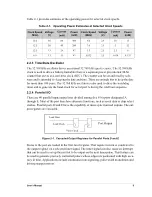
Страница 78: ...32 768 kHz oscillator is normally used to clock the watchdog timer the battery back able time date clock and the periodic interrupt The main oscillator can be shut down in a special low power mode of...

Страница 79: ...heral clock from the main oscillator divided by eight 001 Processor clock from the main oscillator divided by eight Peripheral clock from the main oscillator without divider 01x Processor clock from t...

Страница 80: ...frequencies Table 7 2 Global Clock Double Register GCDR adr 0x0F Bit s Value Description 7 3 xxxxx These bits are ignored 2 0 000 The clock double circuit is disabled 001 8 ns nominal low time 010 10...

Страница 81: ...pply voltage of 5 V and a temperature of 25 C The doubled clock low time increases by 20 when the voltage is reduced to 4 V and increases by about 40 when the voltage is reduced further to 3 3 V The v...

Страница 82: ...ower management scheme 7 4 Controlling Power Consumption The processor power consumption can be traded against speed by slowing the system clock adding wait states using low power consumption instruct...

Страница 83: ...ivided by 2 10 CLK pin is low 11 CLK pin is high 5 4 00 STATUS pin is active low during a first opcode byte fetch 01 STATUS pin is active low during an interrupt acknowledge 10 STATUS pin is low 11 ST...

Страница 84: ...than the RTC there is the possibility of performing a transfer to the holding registers while a carry is taking place resulting in incorrect information In order to prevent this the processor should...

Страница 85: ...xcept code 0x80 0x40 Arm RTC for a reset with code 0x80 or reset and byte increment function with code 0x0C0 0x80 Resets all six bytes of the RTC counter to 0x00 if proceeded by arm command 0x40 0xC0...

Страница 86: ...o use extreme care in writing software to hit the watchdog timer or to turn off the watchdog timer The programmer should not sprinkle instructions to hit the watch dog timer throughout his program bec...

Страница 87: ...ums If these go wrong go into an endless loop with interrupts off Table 7 9 Watchdog Timer Test Register WDTTR adr 0x09 Bit s Value Description 7 0 0x51 Clock the least significant byte of the WDT tim...

Страница 88: ...es in progress to be completed before the reset sequence completes and the clocks switch to divide by eight mode During reset all of the memory control signals are held inactive After the RESET signal...

Страница 89: ...tput High Operational as IFTCH1 SMODE 1 0 Input Not Affected Not Affected CS0 Output High Operational CS1 Output High High CS2 Output High High OE0 Output High Operational OE1 Output High High WE0 Out...

Страница 90: ...hown in Table 7 11 Table 7 11 Peripheral Device Address and Interrupt Vectors On Chip Peripheral ISR Starting Address System Management periodic interrupt IIR 0x00 Memory Management No interrupts Slav...

Страница 91: ...and no interrupt takes place This is shown in Table 7 12 The priorities shown in this table apply only for interrupts of the same priority level and are only meaningful if two interrupts are requested...

Страница 92: ...e needs to be present for a least three peripheral clocks to be detected When the interrupt takes place both pulse catchers associated with that interrupt are auto matically reset If both edges are de...

Страница 93: ...e signal line is needed for each device so that the proces sor can determine which devices are requesting an interrupt The following code shows how the interrupt service routines can be written Extern...

Страница 94: ...operates and bytes must be transferred often enough to prevent the watchdog timer from timing out Bootstrap operation is terminated when the SMODE pins are set to zero The SMODE pins are sampled just...

Страница 95: ...set ends and the bootstrap mode begins TXA will be low reflecting its function as a parallel port output bit that is cleared by the reset This may be interpreted as a break signal by some serial commu...

Страница 96: ...90 Rabbit 2000 Microprocessor...

Страница 97: ...d thus vanish from the memory map The four segments are shown in the example in Figure 8 2 The segment size register SEGSIZE determines the boundaries marked in the diagram The extended code seg ment...

Страница 98: ...reate a 20 bit address Wraparound occurs if the addition would result in an address that does not fit in 20 bits Table 8 1 Segment Registers Segment Register Function XPC Locates extended code segment...

Страница 99: ...e dispatched to the memory chips connected to the Rabbit There are three separate chip select output lines CS0 CS1 and CS2 that can be used to select one of three different memory chips A field in the...

Страница 100: ...te adds to these numbers Wait states should only be used for memory data accesses RAM or data flash not for memory from which instructions are executed code memory Bits 5 4 These bits allow the upper...

Страница 101: ...and is currently available in the Rabbit 3000 Designers Handbook 8 3 2 2 CS1 Enable The optional enable of CS1 is valuable for systems that are pushing the access time of battery backed RAM By enablin...

Страница 102: ...Allocation normally con tinues to the end of the flash memory Data variables are allocated to RAM working backwards in memory Allocation normally starts at 52K in the 64K D space and continues The 52K...

Страница 103: ...The 16 bit PC controls the address of the instruction usually in the region E000 to FFFF The advantage of paged access is that most instructions continue to use 16 bit addressing Only when an out of...

Страница 104: ...98 Rabbit 2000 Microprocessor Figure 8 4 Compilation of Code Segments in Extended Memory Memory View in 8K window each segment E000 FFFF E000 FFFF 4K pages...

Страница 105: ...port serial data I O Port D 4 bits shared with alternate I O pins for serial ports A and B 4 bits not shared Port D has the ability to configure its outputs as open drain outputs Port D has output pre...

Страница 106: ...t A is set up as an input port on reset When the port is read the value read reflects the voltages on the pins 1 for high and 0 for low This could be different than the value stored in the output regi...

Страница 107: ...whether the slave port is enabled PB0 reflects the input of the pin unless serial port B has its internal clock enabled which causes this line to be driven by the serial port clock PB1 reflects the i...

Страница 108: ...s inputs and the source of the serial port inputs for these serial ports depends on the setup of the corresponding serial port control register When serving as serial inputs the data lines can still b...

Страница 109: ...er registers associated with port D are not initialized on reset The following registers are described in Table 9 8 and in Table 9 9 PDDDR Parallel port D data direction register A 1 makes the corresp...

Страница 110: ...of the upper and lower nibble of the final output register of the port On reset bits 0 1 4 and 5 are reset to zero Figure 9 1 Parallel Port D Block Diagram PD7 PD4 I O Data perclk 2 Timer A1 Timer B1...

Страница 111: ...ir out dir out dir out PDB0R W adr 0x068 x x x x x x x PD0 PDB1R W adr 0x069 x x x x x x PD1 x PDB2R W adr 0x06A x x x x x PD2 x x PDB3R W adr 0x 06B x x x x PD3 x x x PDB4R W adr 0x06C x x x PD4 x x...

Страница 112: ...the slave port is enabled Each of the port E out puts can be configured as an I O strobe In addition four of the port E lines can be used as interrupt request inputs The output registers are cascaded...

Страница 113: ...el port E control register This register is used to control the clocking of the upper and lower nibble of the final output register of the port On reset bits 0 1 4 and 5 are reset to zero Table 9 10 P...

Страница 114: ...x x x PE0 PEB1R W adr 0x079 x x x x x x PE1 x PEB2R W adr 0x07A x x x x x PE2 x x PEB3R W adr 0x07B x x x x PE3 x x x PEB4R W adr 0x07C x x x PE4 x x x x PEB5R W adr 0x07D x x PE5 x x x x x PEB6R W a...

Страница 115: ...or addresses occupying 1 8th of the 64K external I O address space Figure 10 1 External I O Bus Cycles Table 10 1 shows how the eight I O bank control registers are organized Table 10 1 I O Bank Contr...

Страница 116: ...I O read or write cycles are two clocks long The I O strobes greatly simplify the interfacing of external devices On reset the upper 5 bits of each register are cleared Parallel port E will not outpu...

Страница 117: ...ns but it can not generate the baud clock Timer B is more flexible when it can be used because the pro gram can read the time from a continuously running counter and events can be programmed to occur...

Страница 118: ...the next input pulse instead of a count being performed The reload registers may be reloaded at any time since the peripheral clock is synchronous with the processor clock Timers A4 A5 A6 and A7 alway...

Страница 119: ...O Registers The I O registers for Timer A are listed in Table 11 1 The control status register for Timer A TACSR is laid out as shown in Table 11 2 Bits 1 4 7 Read write terminal count reached on time...

Страница 120: ...he value in the reload register can be changed while the timer is running to change the period of the next timer cycle When the reload register is initialized the contents of the countdown counter may...

Страница 121: ...er power up and one for after using the Timer B match register system After power up or reset the value in the TBLxR match register is flagged as invalid At this time a value written to the holding re...

Страница 122: ...g TBCMR BE R x Timer B Count LSB Reg TBCLR BF R x Table 11 5 Timer B Control and Status Register TBCSR adr 0x0B0 Bits 7 3 Bit 2 Bit 1 Bit 0 Not used 1 A match with match register 2 was detected This b...

Страница 123: ...erent register than the lower 8 bits The following method is suggested 1 Read the lower 8 bits 2 Read the upper 2 bits 3 Read the lower 8 bits again 4 If bit 7 changed from 1 to 0 between the first an...

Страница 124: ...errupt If the system clock is 20 MHz the counter can count as fast as 10 MHz The uncertainty in a pulse width measure ment can be nearly as low as 38 clocks 2 x 19 or about 2 s for a 20 MHz system clo...

Страница 125: ...ble to perform a cold boot of the micropro cessor system Figure 12 1 shows a block diagram of the serial ports Figure 12 1 Block Diagram of Rabbit Serial Ports The individual serial ports are capable...

Страница 126: ...the clocked serial mode when the internal clock is used Timers A4 A7 supply the input clock for Serial Ports A D These timers can divide the frequency by any number from 1 to 256 see Chapter 11 The i...

Страница 127: ...eration is performed to the serial port status regis ter This bit will request an interrupt on the transition from 1 to 0 if interrupts are enabled Bit 2 Transmitter busy bit This bit is set if the tr...

Страница 128: ...rt C function register PCFR and the parallel port D function register PDFR are used to enable the Port C and Port D serial outputs see Section 9 3 Parallel Port C and Section 9 4 Parallel Port D for m...

Страница 129: ...12 3 Generation of Serial Port Interrupts The receive interrupt request flip flop is set after the stop bit is sampled on receive nomi nally one half of the way through the stop bit Data bits are tran...

Страница 130: ...return and there will be a final interrupt to give the routine a chance to disable the output buffers as in the case for RS 485 transmission 12 4 Receive Serial Data Timing When the receiver is ready...

Страница 131: ...re provided as 8 bit bursts The transmit shift register advances on the falling edge of the clock The receiver samples the data on the ris ing edge of the clock The serial port can generate the clock...

Страница 132: ...waiting in the data register tagged with the send code The send code is effec tively double buffered To receive a character in internal clock mode the receive shift register should be idle The user th...

Страница 133: ...re generated on the last clock rising edge If the interrupt can be serviced within 1 2 clock there will be no pause in the data rate If it takes the receiver longer to answer then there will be a gap...

Страница 134: ...l Clock In a system where the Rabbit serial clock is generated by an external device the clock sig nal has to be synchronized with the internal peripheral clock perclk before data can be transmitted o...

Страница 135: ...since distinct interrupt flip flops exist for receive and transmit The dispatcher can test the receiver data register full bit to dispatch If this bit is on the interrupt is dispatched for receive ot...

Страница 136: ...t data register port C clears interrupt request IPRES 4 restore the interrupt priority 68 clocks to here to level before interrupt took place more interrupts could now take place but receiver data is...

Страница 137: ...utputs on parallel port D If an RS 485 driver is being used dummy characters can be transmitted by disabling the driver after the stop bit has been sent This is an alternative to the above procedure 1...

Страница 138: ...ter as described in Section B 2 3 Sending a 9th bit in the original Rabbit 2000 chip as a high value required delaying the transmission of the next character by 1 baud effectively providing the 9th bi...

Страница 139: ...rrupt routine must not load the next character for another baud time for example 8 6 s at 115 200 bps or 104 s at 9600 bps At the highest baud rates it makes sense to use a busy wait loop in the inter...

Страница 140: ...burst of 8 clock pulses 12 7 6 Supporting 9th Bit Communication Protocols This section describes how 9th bit communication protocols work 9th bit communication protocols are supported by processors s...

Страница 141: ...s another way to detect the start of a data frame The Modbus protocol requires that data frames begin with a minimum 3 5 character quiet time The receiver uses this 3 5 character gap to detect the sta...

Страница 142: ...136 Rabbit 2000 Microprocessor...

Страница 143: ...figured as slaves can themselves have slaves The master and slave communicate with each other via the slave port The slave port is a physical device that includes data registers a data bus and various...

Страница 144: ...ister is meant If it is necessary to distinguish between registers we will refer to the registers as SPD0R writable by the slave or SPD0R writable by the master A status register can be read by either...

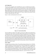
Страница 145: ...rs The figure below shows the sequence of events when the master reads writes the slave port registers Figure 13 2 Slave Port R W Sequencing SCS SD 7 0 SRD Slave Port Read Cycle Slave Port Write Cycle...

Страница 146: ...master Either side that is interrupted can clear the signal that is causing an interrupt request by writ ing to the slave port status register The data bits are ignored but the flip flop that is the...

Страница 147: ...s Each Rabbit in Figure 13 4 has to have RAM memory The master must also have flash memory However the slaves do not need nonvolatile memory since the master can cold boot them over the slave port and...

Страница 148: ...ad or write requests unless the chip select is low If a Rabbit is used as a master this line can be connected to one of the master s programmable chip select lines I0 I7 SRD Input If SCS is also low t...

Страница 149: ...cause of the limited number of lifetime writes to flash memory The slaves reset in Figure 13 4 is under the program control of the master If the master is reset the slave will also be reset because th...

Страница 150: ...the slave port is enabled automatically if SMODE1 SMODE0 lines are set to 0 1 after the reset ends This features disables the normal operation of the processor and causes commands to be accepted via...

Страница 151: ...l servo system solutions may be overly expensive or not work very well because of system nonlinearities The basic communications model for a motion controller is for the master to send short messages...

Страница 152: ...s wired to interrupt the mas ter The acknowledgement message works in a similar manner except that the master writes a dummy character to interrupt the slave to say that it has the character Several p...

Страница 153: ...s on one of the serial ports The slave can interrupt the master at any time by storing to SPD0R It will do this every time an enabled transmitter is ready to accept a character or every time an enable...

Страница 154: ...148 Rabbit 2000 Microprocessor...

Страница 155: ...ontinuing the startup procedure If the clock is battery backed there will be no startup delay since the oscillator is already oscillating The startup delay may be as much as 5 seconds Crys tals with l...

Страница 156: ...768 kHz oscillator This is called the sleepy mode When this is done the power consumption is decreased dramatically The current consumption is often reduced to the region of 100 A at this clock speed...

Страница 157: ...generated by the oscillator This is because the clock doubler uses the inter mediate edge to generate the double frequency If the clock doubler is used to double 14 7456 MHz to 29 4912 MHz the operati...

Страница 158: ...flow At 5 V and a current consumption of 65 mA this would result in about 15 C of self heating and would reduce the maximum clock speed by approximately 3 This reduction is included in Table 15 2 whic...

Страница 159: ...at 5 V and 3 3 V Figure 15 2 Rabbit 2000 Typical Maximum Operating Frequency versus Voltage at 25 C 20 25 30 35 40 45 50 55 50 30 10 10 30 50 70 90 110 Temperature C Maximum Frequency MHz 5 0 V 3 3 V...

Страница 160: ...by 100 for 2 wait states However since only a small proportion of accesses are data accesses rather than code accesses or instruction fetch cycles the overall affect on performance is slight If data m...

Страница 161: ...048 38 7 2 147 140 115 200 24 576 40 7 0 73 66 38 400 23 9616 41 7 0 75 68 57 600 22 1184 45 2 0 82 75 230 400 22 1184 45 2 1 127 120 230 400 22 1184 45 2 2 173 165 230 400 20 2752 49 3 0 90 83 57 600...

Страница 162: ...oints under the same conditions that the mem ory read delays were measured Table 15 3 Memory Read Time Delays Time Delay Output Capacitance 20 pF 70 pF min max min max Clock to address delay Tadr 8 ns...

Страница 163: ...st remain valid following the rising edge of T1 when the clock cycle repeats TDHZV for data write specifies how long the data remain valid once WEx goes high and must be at least one half of a CPU clo...

Страница 164: ...8 ns 14 ns Clock to memory chip select delay TCSx 8 ns 14 ns Clock to I O chip select delay TIOCSx 8 ns 14 ns Clock to I O read strobe delay TIORD 6 ns 12 ns Clock to I O buffer enable delay TBUFEN 8...

Страница 165: ...specified Figure 15 4 I O Read and Write Cycles No Extra Wait States Tadr Tadr External I O Read no extra wait states Thold valid CLK A 15 0 D 7 0 valid Tsetup Thold External I O Write no extra wait s...

Страница 166: ...e cycles The effects are similar for the I O bus read write cycles Figure 15 5 Memory Read and Write with Wait States Tadr Tadr Memory Read one wait state WE Thold CLK A 19 0 D 7 0 Tsetup Thold Memory...

Страница 167: ...V Parameter Description Value Read Parameters Tadr Time from CPU clock rising edge to address valid Max 10 ns 20 pF 19 ns 70 pF Tsetup Data read setup time Min 3 ns Thold Data read hold time Min 0 ns...

Страница 168: ...is the current consumed by the main oscillator which is approximately independent of frequency but varies as the square of the voltage This term is zero when the main oscillator is disabled Some check...

Страница 169: ...t off is given by current A 7 5 V2 4 In low power modes the current consumption is proportional to the square of the voltage At 3 0 V this is approximately 67 A Add the 25 A needed to operate the osci...

Страница 170: ...164 Rabbit 2000 Microprocessor...

Страница 171: ...rom the user s application It occupies space at the bot tom of the root code segment When execution of the user s program starts at address zero on power up or reset it starts in the BIOS When Dynamic...

Страница 172: ...it is possible to substitute a different periodic interrupt This alternative is not supported by Z World since the cost of connecting a crys tal is very small The periodic interrupt keeps the interrup...

Страница 173: ...use virtual watchdogs for other code that must be run periodically If hits to the hardware watchdog are scattered through a program then it may be possible for the code to enter an endless loop where...

Страница 174: ...168 Rabbit 2000 Microprocessor...

Страница 175: ...2 kHz clock speeds simply because there are not enough clock cycles available to service the interrupt Hence virtual watchdogs which depend on the periodic interrupt cannot be used in the sleepy mode...

Страница 176: ...available to read and write I O registers These functions are pro vided for convenience For speed assembly code is recommended For a complete description of the functions noted in this section refer t...

Страница 177: ...I O register A NULL pointer may replace the pointer to a shadow register as an argument to WrPortI and WrPortE the shadow register associated with the port will not be updated A pointer to the shadow...

Страница 178: ...he data bits written are ignored For example a write to the status register in the Rabbit serial ports is used to clear the transmitter interrupt request but the data bits are ignored and the status r...

Страница 179: ...ame oscillator as the real time clock there is no relative gain or loss of time between the two A millisecond timer variable MS_TIMER is also maintained by the Virtual Driver Two utility routines are...

Страница 180: ...174 Rabbit 2000 Microprocessor...

Страница 181: ...gister Moves on page 179 Exchange Instructions on page 180 Stack Manipulation Instructions on page 180 16 bit Arithmetic and Logical Ops on page 180 8 bit Arithmetic and Logical Ops on page 181 8 bit...

Страница 182: ...source Flag Register Key S Z L V The L V logical overflow flag serves a dual purpose L V is set to 1 for logical operations if any of the four most significant bits of the result are 1 and L V is res...

Страница 183: ...arry 100 LZ logical zero 101 LO logical one 110 P sign plus 111 M sign minus Logical zero if all four of the most significant bits of the result are 0 Logical one if any of the four most significant b...

Страница 184: ...I S Z V C Operation LD A BC 6 r s A BC LD A DE 6 r s A DE LD BC A 7 d BC A LD DE A 7 d DE A LD HL n 7 d HL n LD HL r 6 d HL r B C D E H L A LD r HL 5 r s r HL LD IX d n 11 d IX d n LD IX d r 10 d IX d...

Страница 185: ...a 64K page boundary Since the LDP instruc tion operates on two byte values the second byte will wrap around and be written at the start of the page if you try to read or write across a page boundary T...

Страница 186: ...n ADD SP d 4 f SP SP d d 0 to 255 POP IP 7 IP SP SP SP 1 POP IX 9 IXL SP IXH SP 1 SP SP 2 POP IY 9 IYL SP IYH SP 1 SP SP 2 POP zz 7 r zzl SP zzh SP 1 SP SP 2 zz BC DE HL AF PUSH IP 9 SP 1 IP SP SP 1 P...

Страница 187: ...DE 4 f L 0 IY IY DE RL DE 2 fr L CY DE DE CY left shift with CF RR DE 2 fr L DE CY CY DE RR HL 2 fr L HL CY CY HL RR IX 4 f L IX CY CY IX RR IY 4 f L IY CY CY IY SBC HL ss 4 fr V HL HL ss CY cout if s...

Страница 188: ...instruction output inverted carry C is set if A B if the oper ation or virtual operation is A B Carry is cleared if A B SUB outputs carry in opposite sense from SBC and CP 18 11 8 bit Bit Set Reset an...

Страница 189: ...L HL 6 0 HL 7 CY HL 7 RLC IX d 13 f b L IX d IX d 6 0 IX d 7 CY IX d 7 RLC IY d 13 f b L IY d IY d 6 0 IY d 7 CY IY d 7 RLC r 4 fr L r r 6 0 r 7 CY r 7 RR HL 10 f b L HL CY CY HL RR IX d 13 f b L IX d...

Страница 190: ...on clk A I S Z V C Operation LDD 10 d DE HL BC BC 1 DE DE 1 HL HL 1 LDDR 6 7i d if BC 0 repeat LDI 10 d DE HL BC BC 1 DE DE 1 HL HL 1 LDIR 6 7i d if BC 0 repeat If any of the block move instructions a...

Страница 191: ...mn LRET 13 PCL SP PCH SP 1 XPC SP 2 SP SP 3 RET 8 PCL SP PCH SP 1 SP SP 2 RET f 8 2 if f PCL SP PCH SP 1 SP SP 2 RETI 12 IP SP PCL SP 1 PCH SP 2 SP SP 3 RST v 10 SP 1 PCH SP 2 PCL SP SP 2 PC R v v 10...

Страница 192: ...er growing stack RETI pops IP from stack and then pops return address The instruction reti can be used to set both the return address and the IP in a single instruction If preceded by a LD XPC a compl...

Страница 193: ...practical op code The codes that are concerned with decimal arithmetic DAA RRD and RLD could be simulated but the simulation is very inefficient The bit in the status register used for half carry is...

Страница 194: ...LD A IIR was I register The following Z80 Z180 instructions have been dropped and are not supported Alterna tive Rabbit instructions are provided Z80 Z180 Instructions Dropped Rabbit Instructions to U...

Страница 195: ...s IOI and IOE affect source Flag Register Key S Z L V The L V logical overflow flag serves a dual purpose L V is set to 1 for logical operations if any of the four most significant bits of the result...

Страница 196: ...11 C carry 100 LZ logical zero 101 LO logical one 110 P sign plus 111 M sign minus Logical zero if all four of the most significant bits of the result are 0 Logical one if any of the four most signifi...

Страница 197: ...11011101 11011100 4 f L 0 AND IY DE 11111101 11011100 4 f L 0 AND n 11100110 n 4 fr L 0 AND r 10100 r 2 fr L 0 BIT b HL 11001011 01 b 110 7 f s BIT b IX d 11011101 11001011 d 01 b 110 10 f s BIT b IY...

Страница 198: ...7 JP mn 11000011 n m 7 JR cc e 001cc000 e 2 5 JR e 00011000 e 2 5 Note If byte following op code is zero next sequential instruction is executed If byte is 2 11111110 jr is to itself LCALL xpc mn 110...

Страница 199: ...n 11011101 00101010 n m 13 s LD IX SP n 11011101 11000100 n 11 LD IX HL 11011101 01111101 4 LD IX mn 11011101 00100001 n m 8 LD IY mn 11111101 00101010 n m 13 s LD IY SP n 11111101 11000100 n 11 LD IY...

Страница 200: ...011101 11100101 12 PUSH IY 11111101 11100101 12 PUSH zz 11zz0101 10 RES b HL 11001011 10 b 110 10 d RES b IX d 11011101 11001011 d 10 b 110 13 d RES b IY d 11111101 11001011 d 10 b 110 13 d RES b r 11...

Страница 201: ...01011 00100110 10 f b L SLA IX d 11011101 11001011 d 00100110 13 f b L SLA IY d 11111101 11001011 d 00100110 13 f b L SLA r 11001011 00100 r 4 fr L SRA HL 11001011 00101110 10 f b L SRA IX d 11011101...

Страница 202: ...196 Rabbit 2000 Microprocessor...

Страница 203: ...target reset line which should be drivable by an external CMOS driver The STATUS pin is used to by the Rabbit based target to request attention when a breakpoint is encountered in the target under te...

Страница 204: ...eeds to begin or to enable the port and wait for interrupts The SMODE pins can be used for signaling and can be detected by a poll However recall that the SMODE pins have a special function after rese...

Страница 205: ...s board can accept these unsolicited messages using its clocked serial port To prevent overrunning the receiver the target can wait for a handshake signal on one of the SMODE lines or there can be sui...

Страница 206: ...200 Rabbit 2000 Microprocessor...

Страница 207: ...ith a resistor as described in Technical Note TN301 Rabbit 2000 Microprocessor Interrupt Problem c Wait states did not function properly when used to access code in slower mem ories because certain in...

Страница 208: ...visions Furthermore a problem with LDIR LDDR operation and Instruction Data split was discovered These problems are all corrected in the Rabbit 2000C 4 Third revision Rabbit 2000C identified by IQ5T o...

Страница 209: ...op Register for asynch 9 bit operation X X X Added clocked serial command for full duplex operation X X X Improved battery backup hardware X X X Added support for Instruction Data split X X X Implemen...

Страница 210: ...ank 0 Control Register A C MB0CR 0x14 W 00001000 Memory Timing Control Register C MTCR 0x19 W xxxx0000 Global CPU Configuration Register A C GCPU 0x2E R 0xx00000 Rabbit 2000 Global Revision Register A...

Страница 211: ...e GREV register Table B 3 summarizes the processor identification information for the different Rabbit 2000 versions Details of the CPU ID registers are listed in Table B 4 and Table B 5 Table B 3 Rab...

Страница 212: ...m fetch as a function of the SMODE pins read only 1 Ignore the SMODE pins program fetch function 6 5 read These bits report the state of the SMODE pins 4 0 00000 Revision identifier for the Rabbit 200...

Страница 213: ...protocols as well as sending parity for compatibility with legacy systems With the new register data may be conveniently transmitted with either a 1 or 0 bit inserted following the last data bit and t...

Страница 214: ...e ignored in the asynch mode 01 In clocked serial mode start a byte receive operation 10 In clocked serial mode start a byte transmit operation 11 In clocked serial mode start a byte transmit operatio...

Страница 215: ...al Note TN303 Conformal Coatings Figure B 1 Low Power 32 768 kHz Oscillator Circuit The capacitors on either side of the crystal provide the load capacitance which is specified by the crystal manufact...

Страница 216: ...ower is reached when I 7 A RMS It is logical to use the typical effective resistance rather than the maximum total resistance in computing drive power If a particular crystal has a higher resistance t...

Страница 217: ...rties particularly faster subroutine linkage can be expanded to fill up to 52K of root space Formerly both spaces had to share the 52K of space Separate I D space is supported by Dynamic C version 7 3...

Страница 218: ...en read 5 0 Enable A16 and A19 inversion independent of instruction data 1 Enable A16 and A19 inversion controlled by bits 0 3 for data accesses only This enables the instruction data split This is se...

Страница 219: ...ching instructions from address zero of the device connected to CS0 OE0 and WE0 which in most cases is a flash memory If the flash contains 0xff at address zero the pro cessor will decode this as an R...

Страница 220: ...sequent iterations use the number of waits programmed for the memory located at the write address for both the read and write cycles This becomes a problem when moving a block of data from a slow memo...

Страница 221: ...measure EMI spreading the energy of a given harmonic over a wider bandwidth will decrease the amount of EMI measured for a given harmonic The spectrum spreader not only reduces the EMI measured in go...

Страница 222: ...esirable to disable the spreader for low speed oscillators where it is probably unnecessary anyway However in practical cases the whistle may not be audible because of the very low level of the interf...

Страница 223: ...000C but may be disabled The clock low time is controlled by the clock doubler control register and is assumed to be a minimum of 14 ns in the above example Also the maximum clock speed from the exam...

Страница 224: ...ecifica tions Table B 12 Memory Timing Control Register Memory Timing Control Register MTCR Address 0x19 Bit s Value Description 7 4 xxxx These bits are reserved and should not be used 3 0 Normal timi...

Страница 225: ...tems intended for sur gical implantation into the body or to sustain life and whose failure to perform when properly used in accordance with instructions for use provided in the labeling and user s ma...

Страница 226: ......

Страница 227: ...ad and write timing 58 external interrupts control registers 86 G generating pulses 42 I instructions 22 175 alphabetic order 189 arithmetic and logical ops 26 I O instructions 29 load to constant add...

Страница 228: ...16 GCM1R 216 GCMxR 204 GCPU 204 205 GCSR 73 GOCR 77 GREV 204 205 206 I O bank control 109 I O registers 65 IBxCR 109 index registers 14 interrupt priority register 14 interrupts 35 MB0CR 204 213 MBxCR...

Страница 229: ...recommendations 129 synchronous serial port 208 transmit serial data timing 124 transmitting and detecting breaks 131 transmitting dummy charac ters 131 slave port 46 137 applications 145 hardware de...

Страница 230: ...224 Rabbit 2000 Microprocessor...

Отзывы: