


无锡人人行拍网络科技有限公司
10
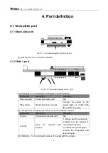
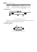
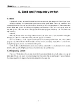
Fig.4.1.4.2 schematic diagram of bottom power welding pad port
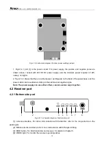
1. Fig.4.1.4.1 port [1] is the power socket: For power supply, the positive and negative poles are
shown above, connect with 9V~16V DC power supply, and the minimum power required is 12W,
namely 12V @1A.
2. Fig.4.1.4.2 shows that there is a direct power welding pad on the back of the power base, and the
power cable can be welded according to the positive and negative signs.
Note: The power supply can use either of two, cannot use two ways together.
4.2 Receiver port
4.2.1 Bottom side port
1 2 3 4 5 6 7 8
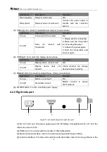
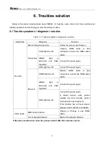
Fig.4.2.1.1 schematic diagram of bottom side port
[1]: Antenna interface, For data communication with transmitter, refer to the long antenna in the
packing list.
[2]: Mobile antenna interface, refer to the small antenna with 90°angle in fitting.
[3]: BIND button, For bind transmitter and receiver, for details in Chapter 5.
[4]: WORK light, For monitor the receiver operating status.


