

无锡人人行拍网络科技有限公司
8
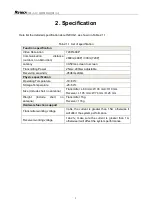
4. Port definition
4.1 Transmitter port
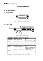
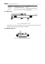
4.1.1 Back side port
1
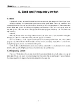
Fig.4.1.1.1 schematic diagram of back side port
[1]: Camera port: For connect the camera.
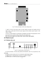
4.1.2 Side 1 port
1 2 3
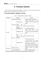
Fig.4.1.2.1 schematic diagram of side 1 port
[1]: Work light, For monitoring the transmitter operating status.
Light status
Description
Operation
Flash regularly
Transmitter works well
NA
Other status
Transmitter does not work
Connect the system to the
power again, or contact with
the customer service.
[2]: Link light, For monitoring the status of connect with the receiver.
Light status
Description
Operation
Turn-on
Connect with receiver well
NA
Turn-off
Does
not
connect
with
receiver
1. Please wait for connecting
2. Make sure the receiver is
connected the power.
3. Connect the power again
4. Bind the Transmitter and
receiver again
[3]: CAM light
:
For monitoring the status of connect with the camera.


