


Version 09.12.2020
HW: CAM(V100)/(V11+V41)
ab Serien Nr: NZ20NOV694
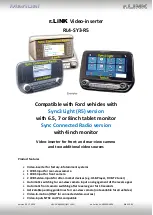
RL4-SY3-R5
P
a
g
e
2
Contents
1.
Prior to installation
1.1.
Delivery contents
1.2.
Checking the compatibility of vehicle and accessories
1.3.
Connectors
–
video interface
1.4.
Dip switch settings
1.4.1.
8 dip
–
black
1.4.1.1.
Activating the front camera input (dip 1)
1.4.1.2.
Enabling the in
terface’s video inputs (dip 2
-3)
1.4.1.3.
Activation of the Interface PDC Graphic (Dip 4)
1.4.1.4.
Rear-view camera setting (dip 5)
1.4.1.5.
Activating the guide lines (dip6)
1.4.1.6.
Monitor selection (Dip 7)
1.4.2.
4 dip - red
2.
Installation
2.1.
Place of installation
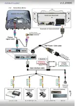
2.2.
Connection schema
2.3.
Connection - picture signal cable
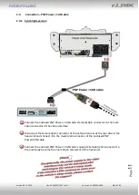
2.4.
Connection
–
PNP Power / CAN cable
2.4.1.
Sync3 light-version
2.4.2.
Sync3 full version as ALL-IN-ONE head-unit
2.4.3.
Sync3 full version with separate APIM module
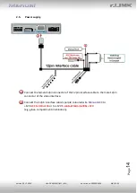
2.5.
Power supply
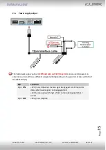
2.6.
Power supply output
3.
Connection
–
video sources
3.1.
Audio insertion
3.2.
After market front camera
3.3.
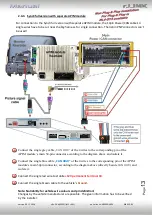
After-market rear-view camera
3.3.1.
Case 1: Interface receives the reverse gear signal
3.3.2.
Case 2: Interface does not receive the reverse gear signal
3.4.
Connection video-interface and keypad
3.5.
Picture settings
4.
Interface operation
4.1.
By infotainment button
4.2.
By keypad
5.
Specifications
6.
FAQ
–
Trouble Shooting-Interface functions
7.
Technical support


