


Version 09.12.2020
HW: CAM(V100)/(V11+V41)
ab Serien Nr: NZ20NOV694
RL4-SY3-R5
P
a
g
e
18
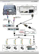
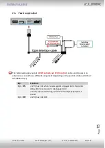
3.3.
After-market rear-view camera
Some vehicles have a different reverse gear code on the CAN-bus which
doesn’t
communicate with the
interface’s CAN
. In this case there are two different ways of
installation. If the
interface’s
CAN is able to detect
an enabled vehicle’s reverse gear, the
green wire of the 6pin to 12pin cable should carry +12V while the reverse gear is engaged.
Note:
Do not forget to set dip5 of video-interface to ON before testing.
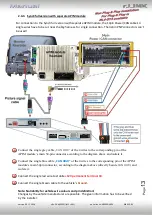
3.3.1.
Case 1: Interface receives the reverse gear signal
If the interface re12V on the green wire of the 12pin interface cable while reverse
gear is engaged, the video interface will automatically switch to the rear-view camera input
“
CAMERA-
IN”
while the reverse gear is engaged.
The 12 V power supply for the rear-view camera (max 3A) has to be taken from the
12pin
interface cabl’s
green wire
“Reverse
-
OUT”
to avoid an unnecessary,
permanent power supply to the camera electronic.
Both green cables
“Reverse IN”
and
“Reverse OUT”
have to remain connected.


