Instruction book
2012 2039 28
116
Preparation for New Seal Installation
Inspect the compressor shaft for burrs or deep scratches at the wear sleeve area. Using a 100-grit emery
cloth, lightly sand horizontally any rust or Loctite™ on the shaft. Using a fine file or emery cloth, deburr
the key area of the rotor shaft. Cover the keyway with masking tape to prevent damage to the new seal
during installation.
Clean the seal adapter with fast drying solvent. Assure that the scavenge drain in the seal adapter is
clean and open. Place the outer face of the seal adapter on a flat, hard surface.
Remove the new triple lip seal from the package and inspect for damage or imperfections on the seal lips.
Apply a thin coat of Loctite™ 290 to the outer steel case of the seal and position the seal in the seal
adapter bore.
Insert the proper seal driver over the seal. Insert the proper wear sleeve driver in the seal driver and tap
the new seal into the bore with a medium sized hammer.
Preheat the wear sleeve (in a small oven) to 350°F. Do not preheat in warm oil.
Apply a thin film of Loctite™ to the inner diameter of the wear sleeve and immediately install on the
compressor shaft using the proper wear sleeve driver. Drive the wear sleeve on the shaft until the driver
bottoms on the shaft shoulder.
Seal Installation
Apply a thin coat of compressor fluid to the outer face of the wear sleeve and seal lip.
Slide the proper seal installation sleeve against the wear sleeve with the taper toward the end of the rotor
shaft.
Install a new O-ring on the seal adapter and lubricate with compressor fluid.
Install a new O-ring around the scavenge port (use petroleum jelly to hold the O-ring on the seal adapter
face during installation).
Carefully slide the seal adapter with the new seal installed over the end of the rotor shaft and up against
the adapter bore.
Using care not to damage the O-ring, evenly draw the adapter into the bore, install the four retaining bolts
and tighten to the specified torque.
Remove the installation sleeve.
Apply a thin film of compressor fluid to the O-ring and seal lip of the outer fluid slinger.
Install the outer slinger over the end of the rotor shaft and push into the scavenge bore using both
thumbs.
Reinstall drive motor, and coupling.
Reinstall the coupling guards before starting the compressor.
Содержание QGV 40
Страница 2: ......
Страница 16: ...Instruction book 2012 2039 28 16 Main components Main components...
Страница 53: ...Instruction book 2012 2039 28 53 Text on figure Reference Designation 1 General 2 Language in use...
Страница 100: ...Instruction book 2012 2039 28 100 Electric cubicle layout fixed speed Electric cubicle layout Variable speed...
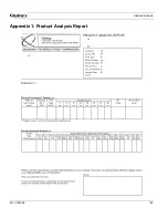
Страница 128: ...Instruction book 2012 2039 28 128 Appendix 1 Product Analysis Report...
Страница 131: ......


