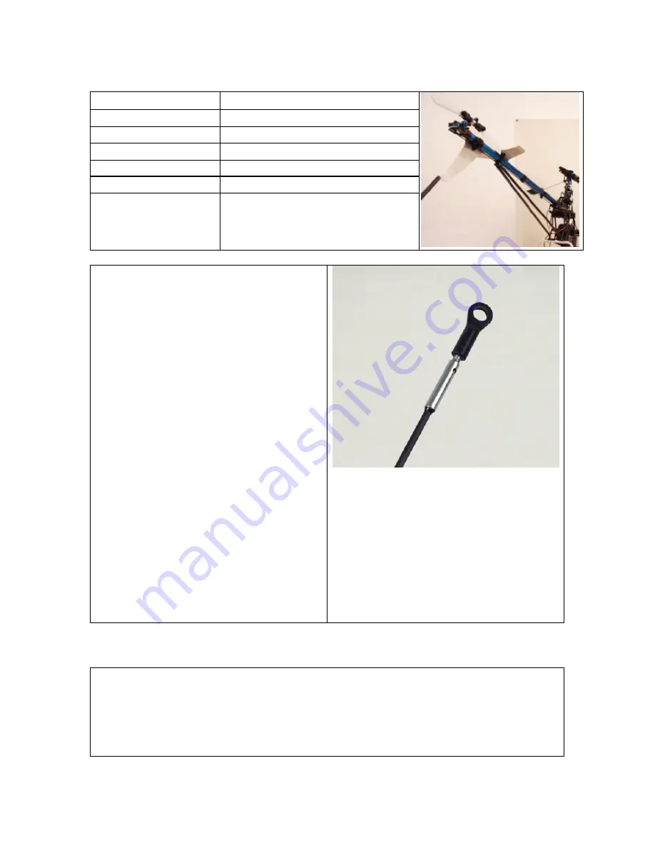
Step 2- Rudder Push Rod Assembly
Rod Use
Rudder Servo to Tail Pitch Change Lever
Linkage ID Letter
H
# of Rods
1
Rod Size
N/A
Ball Link 1
Medium
Ball Link 2
Medium
Center to Center
615.95mm
Construct the Rudder push rod with (2)
Machined Carbon Push Rod Ends &
(1) Carbon push rod cut the rod to
length and epoxies the ends on finish
with (2) Medium Ball Links. Use the (3)
Tail Control Rod Guides, (3) Tail
Control Rod Guides inserts, & (3) Tail
Control Rod Guides inserts B. The
three tail control rod guides are epoxies
together to make complete assemblies.
Space the assemblies evenly about the
boom and use CA Glue to attach them.
Note:
??
The Carbon Rod will have to be
cut to length.
??
The second end will have to
attached after the rod is installed
into the Guides
Replacement Part #:
Tail Control Rod – HHI4072
Tail Rudder Guide Set – HHI2900
Step 3 – Radio Setup
General Information:
First, change your radio to 3 Point, 120 Degrees swash-plate mixing. My advice
is to read your radio manual for proper adjustment of the swash mixing. After you
have the radio gear installed, the basic guidelines for proper setup of an EMS
system is everything must be 90 Degrees and Parallel with all control sticks in
the center. After all linkages are installed and everything meets the above


