15
WARNING: QUICK nautic water heaters are
provided with a double thermostat with manual
reset that shuts down power supply in case of an
excessive water temperature.
If it happens, follow the instructions below:
• shut down power supply.
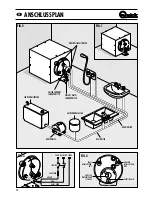
• Remove the protection cover (19) in order to reach the
thermostat (16).
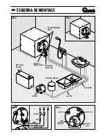
• Push on the reset button on the double thermostat
(fig. 4).
• Replace on the protection cover (19).
• Switch on power supply.
WARNING: if the high temperature safety works
repeatedly, call QUICK service center.
MAINTENANCE
We recommend checking the magnesium anode (6)
every 24 months. Replace the anode if its size has been
reduced significantly. This simple and preventive
maintenance will ensure a long life of the equipment.
During wintertime, when the water heater is not
in use it should be drained using the lever of the
valve (26). This is to avoid serious damage
caused by freezing.
Periodically check the joints of the water pipe installation;
check the tightness of the securing screws and replace
them in case they are worn or corroded.
Also periodically check the safety of the electrical
installation.
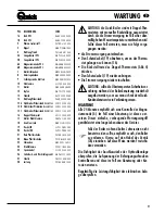
POS. DESCRIPTION
CODE
1A
Tank 23L
M L B 2 3 S 0 0 0 0 0 0
1B
Tank 42L
M L B 4 2 S 0 0 0 0 0 0
2
Thermal insulating
P E T B P L 1 3 2 2 0 0
3
Nipless
M N N P 1 2 M M T 0 0 0
4
Flange gasket
P G F L A N G B 1 8 6 0
5A
Hot water output pipe 23L
M N P S 2 3 L 0 0 0 0 0
5B
Hot water output pipe 42L
M N P S 4 2 L 0 0 0 0 0
6A
Magnesium anode 23L
MMANMG230000
6B
Magnesium anode 42L
MMANMG420000
7
Bolts
M B V 0 8 3 0 M Z U 0 0
8
Washer
M B R 0 8 X 0 0 0 0 0 0
9
Squagging nuts
M B D 0 8 M X E T 0 0 0
10
Ground cable terminal
E J C Y 0 4 0 0 0 0 0 0
11
Nut
M B D 0 8 M X E N 0 0 0
12
Cap
M N T P 1 2 T 0 0 0 0 0
13
Flange
M L F 2 3 0 0 0 0 0 0 0
14
Element gasket
P G G R E S 0 0 0 0 0 0
15 A Electric element
1200W 220V
E V R 1 2 2 2 0 0 0 0 0
15 B Electric element
500W 220V
E V R 0 5 2 2 0 0 0 0 0
15 C Electric element
1200W 110V
E V R 1 2 1 1 0 0 0 0 0
16
Bi-Thermostat
E V T 1 5 S 0 0 0 0 0 0
17
Cable-press nut
P B D P G 1 1 G 0 0 0 0
18
Joint
M N R C 1 2 M F 5 0 T 0
19
Cover SX
S L P E C P B R S X 0 0
20
Cover DX
S L P E C P B R D X 0 0
21
Red plastic washer
P E C R B L R S 0 0 0 0
22
Blue plastic washer
P E C R B L B L 0 0 0 0
23
Screw
M B V 0 2 9 1 3 A X C C
24
Cable outlet
P P P G 1 1 B 0 0 0 0 0
25
Power supply cable
E C C 3 0 2 5 0 G 0 0 0
26
Relief/non return valve
M N V A L S 1 2 S 6 0 0
27
Hose clamp
P B F 2 5 1 0 0 W 0 0 0
28
Discharge pipe
P V T B G M 5 N T 0 3 0
F
MAINTENANCE


