background image

BI 7.2.3-44

Nov-2017, Rev 2

6

1

3

4

6

2

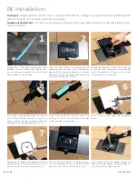
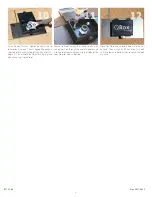
Remove Nails:  Use roofing bar to break seals 

between 1st and 2nd and 3rd shingle courses.  

Be sure to remove any obstructing nails to allow 

correct placement of the QBox.

7

Slide the QBox flashing up underneath the 

second course of shingles, so that the bottom 

edge of the flashing does not overhang the front 

edge of the shingle and the top edge extends up 

under the third course of shingles.

Mark Conduit Location: If not using attic conduit 

exit, skip to step 6.  Otherwise, mark the location 

to drill the conduit pass-through with a lumber 

crayon or other marking device.

Drill Conduit Hole: Remove QBox flashing and 

drill 1" hole at location marked in Step 3. Use 

either a spade bit or hole saw. Avoid all electrical 

components on underside of deck in the attic.

Reinstall Flashing: Reinstall the QBox assembly 

such that the conduit fitting in the center of the 

box aligns with the hole you created in step 4. 

IV. 

Installation

5

Clean: Clean debris from roof to ensure the 

flashing is as flat as possible against the roof 

surface and clean for adhesion.

7

8

Caulk: Fill the fastener holes with appropriate 

sealant.

Tool Specs: 

Shingle ripper bar, lumber crayon, 1" spade pit, hand broom, caulk gun, appropriate sealant, adjustable wrench 

with 1.25" capacity, 1/2" nut driver, #3 phillips screw driver.    

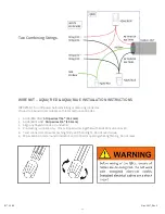
Side Mount Conduit Exit:  

For side mount conduit exit, where transition wires leave the QBox from the side of the box, skip 

steps 3-5 and 8-10.

9

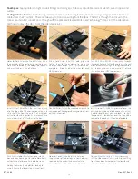
Install Conduit: Install your conduit through the 

QBox and the roof. Loosen the compression nut 

to install conduit, but don't remove.

Optional Caulk:  Apply an upside down U-shaped 

bead of sealant to the underside of the flashing 

before insertion.  Do not use excessive sealant.

Содержание QBox

Страница 1: ...QBox R E S P E C T T H E R O O F Patented Junction Box For Composition Asphalt Shingle Roofs Installation Manual Elevated Water Seal Technology U S Patent No 9 496 697 9 742 173...

Страница 2: ...ns 1 I II Safety Callouts 1 I III Safety Warnings and Cautions 2 II Product Description 4 II I Overview 4 I II Dimensions 4 I III QBox Contents 5 III Installation Overview 6 II I QBox Location 6 IV In...

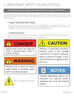
Страница 3: ...is installation manual I I SAVE THESE INSTRUCTIONS This manual contains important instructions that shall be followed during installation and maintenance of the system This manual should be stored nea...

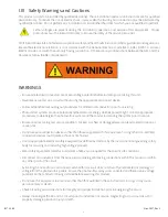
Страница 4: ...od service condition Nicked pinched or damaged wires can lead to electrocution or cause a fire Do not use wire connection devices other than those supplied with this equipment Using other non certifie...

Страница 5: ...cified in this manual Use only wire combinations specified in this manual Use proper safety and personal protective equipment PPE such as goggles and safety glasses gloves ear protection hard hats saf...

Страница 6: ...le and weather resistant polycarbonate With excellent impact resistance and a wide operating temperature range this product is suitable for all environments In addition since it is made of nonconducti...

Страница 7: ...eeds Strain relief fittings for PV homerun wires for sidewall pass through EMT conduit for transition wiring for attic pass through Conduit connectors and fittings for transition wiring for sidewall p...

Страница 8: ...nder a module that is easy to lift out of position for access III Installation Overview The QBox utilizes a patented waterproof pass through for EMT to run system wires through the roof into the attic...

Страница 9: ...nderside of deck in the attic Reinstall Flashing Reinstall the QBox assembly such that the conduit fitting in the center of the box aligns with the hole you created in step 4 IV Installation 5 Clean C...

Страница 10: ...s will hold the QBox flashing in place when securing it to the roof Secure to Roof Screw the anchor bolts with sealing washers through the mounting holes and into the roof sheathing securing the QBox...

Страница 11: ...be used to maintain an electrical bond between fittings Ensure all proper jumpers or other bonding mechanisms are in place per NEC The DC input and DC output circuits are isolated from the enclosure...

Страница 12: ...ieve one of the approved wiring combinations outlined in Section VI 10 8 Install Grommet Slide the grommet over the wires and push it down into the conduit such that it extends over the cut edge and l...

Страница 13: ...diagrams for all the approved use cases All wires are to be copper conductors with insulation rated to 90 C or higher Maximum size of incoming PV string wires is 10 AWG Maximum size of outgoing branc...

Страница 14: ...local and national codes 1 AQUA RED ONLY Strip wires 7 16 11 1mm 2 AQUA BLUE ONLY Strip wires 3 4 19 1mm 3 Align any frayed strands or conductors 4 Pre twisting is unnecessary Place stripped wires to...

Страница 15: ...D x 2 6 H Flashing 12 W x 12 D Ambient Operating Conditions 35 C 75 C Testing has shown that there is a 25 5 C increase in box temperature over ambient when wind speed is less than 1 mps and solar irr...

Страница 16: ...BI 7 2 3 44 Nov 2017 Rev 2 925 478 8269 2700 Mitchell Dr Walnut Creek CA 94598 2017 by Quick Mount PV All rights reserved R E S P E C T T H E R O O F www quickmountpv com tech quickmountpv com...

Отзывы: