Smart Wi-Fi Module Series
SC20-WL Hardware Design
SC20-WL_Hardware_Design
24 / 81
V
OL
max=0.37V
V
OH
min=2.2V
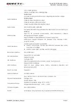
SD_DATA0
41
IO
High speed
bidirectional digital
signal lines of SD
card
1.8V SD card:
V
IL
max=0.58V
V
IH
min=1.27V
V
OL
max=0.45V
V
OH
min=1.4V
2.95V SD card:
V
IL
max=0.73V
V
IH
min=1.84V
V
OL
max=0.37V
V
OH
min=2.2V
SD_DATA1
42
IO
SD_DATA2
43
IO
SD_DATA3
44
IO
SD_DET
45
DI
SD card insertion
detection
V
IL
max=0.63V
V
IH
min=1.17V
Active low
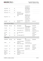
Touch Panel (TP) Interface
Pin Name
Pin No.
I/O
Description
DC
Characteristics
Comment
TP_INT
30
DI
Interrupt signal of TP
V
IL
max=0.63V
V
IH
min=1.17V
1.8V power
domain.
TP_RST
31
DO
Reset signal of TP
V
OL
max=0.45V
V
OH
min=1.35V
1.8V power
domain. Active low.
TP_I2C_
SCL
47
OD
I2C clock signal of
TP
1.8V power
domain.
TP_I2C_
SDA
48
OD
I2C data signal of TP
1.8V power
domain.
LCM Interface
Pin Name
Pin No.
I/O
Description
DC
Characteristics
Comment
PWM
29
DO
Adjust the backlight
brightness.
PWM control signal.
V
OL
max=0.45V
V
OH
max=VBAT_BB
LCD_RST
49
DO
LCD reset signal
V
OL
max=0.45V
V
OH
min=1.35V
1.8V power
domain.
Active low.
LCD_TE
50
DI
LCD tearing effect
signal
V
IL
max=0.63V
V
IH
min=1.17V
1.8V power
domain.
MIPI_DSI_
CLKN
52
AO
MIPI DSI clock signal
(negative)
MIPI_DSI_
CLKP
53
AO
MIPI DSI clock signal
(positive)


