


Automotive Module Series
AG521R-NA QuecOpen
Hardware Design
AG521R-NA_QuecOpen_Hardware_Design 42 / 92
3.6.3.
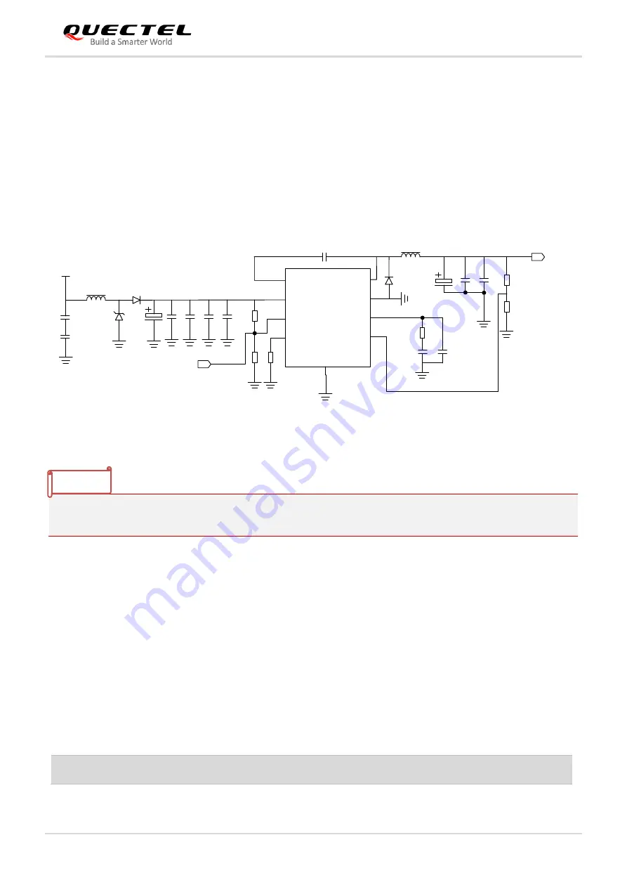
Reference Design for Power Supply
Power design for the module is very important, as the performance of the module largely depends on the power
source. If the voltage drop between the input and output is not too high, it is recommended to use an LDO to supply
power for the module. If there is a big voltage difference between the input source and the desired output (VBAT),
a buck converter is preferred to be used as the power supply.
The following figure shows a reference design for 12/24 V input power source. The designed output for the power
supply is about 3.8 V and the maximum rated current is 5 A.
2
4
1
3
6
7
8
1
8
2
K
NM
1
0
0
K
1
0
p
F
1
0
0
p
F
1
0
0
n
F
1
0
µ
F
470 µF
1
0
0
n
F
1
0
0
n
F
DC_IN
100 µH
5V_EN
100 nF
BOOT
VIN
EN
RT/CLK
SW
GND
COMP
FB
G
N
D
TPS54 560-Q1
7. 2 µH
9
5
220 µF
1
µ
F
1
0
n
F
4
.3
K
4
.7
n
F
4
.7
p
F
7
5
k
2
0
k
DC_3V8
Figure 9:
12/24 V Power Supply System Reference Design
To avoid damaging internal flash, do not switch off the power supply when the module works normally. Only after
the module is turned off by PWRKEY, the power supply can be cut off.
3.6.4.
Monitor the Power Supply
API can be used to monitor the VBAT_BB voltage value. For more details, see
document [2]
.
3.7.
Power on and off Scenarios
3.7.1.
Turn on Module with PWRKEY
Table 8: PWRKEY Pin Description
Pin Name Pin No.
Description
DC Characteristics
Comment
NOTE


