QUATRO
Air Technologies Inc.
----------------------------------------------------------------
Engineers Of Clean Air
----------------------------------------------------------------
30 Hymus Boulevard, Montreal, Quebec, H9R 1C9 Tel.: (514) 630-4444 Fax: (514) 630-4454 website:
www.quatroair.com
SAFETY PRECAUTIONS
Carefully read instructions in this manual before operation (keep manual as it contains information for proper operation and maintenance). Keep all fastening
hardware tight to ensure that the unit is in safe working condition. Familiarise yourself with the way in which the special filter is removed, installed, and serviced.
Filter must be in place whenever this machine is in operation. Use only on grounded electrical circuit; do not use two-wire electrical prong adapters to defeat the
three-pronged plug on the end of the cord. When servicing motor, be careful when touching exterior of motor when it is turned off; it may be hot enough to be
painful or cause injury.
Do not substitute any other filter for the one supplied, as it will alter the design characteristics.
UNPLUG UNIT FROM ITS
POWER SUPPLY PRIOR TO SERVICING UNIT!
Ensuring Proper Grounding of ABS/PVC Fittings and Tubing for a Dust Collection System.
For dust collection systems, galvanized metal pipe and fittings are best, but for most typical applications, fittings and dust collection tubing made of plastic (ABS
or PVC) are sufficient, provided they are
properly grounded
to dissipate static electrical charges. Dust and air in the right proportions can be an explosive
mixture, and a build up of static electricity can provide the spark to ignite it.
To safely collect and bleed off the static charge, bare copper wire (not insulated) should be run along the inside of the duct-work and be attached to grounding
screws or a bare metal surface on both the dust collector and the unit that it is connected to (if it is connected to a unit). The power cords of both machines must
be terminated in a grounded three-prong plug to complete the connection to the ground. Wires over the irregularities of fittings, especially at “Y”s or “T”s could
form traps for particles. Therefore, bypass the fittings by running the wires to the outside through small holes. Seal the holes with silicone caulking compound
and join the wires by twisting them together and securing them with a wire nut. As charges can also collect on the outside surface, we recommend wrapping
bare copper wire in a spiral around the outside of the ductwork, securing it with electrical tape and connecting it to the ground system by means of wire nuts. If
you have any difficulty securing the hose clamp to the hose and fittings, try wrapping the joints with duct tape first to provide a good gripping surface. If you are
still having difficulty in obtaining a safe electrical ground, we recommend the services of a good electrician.
UNIT INSPECTION
Upon receipt, inspect unit for either visible or concealed damage. Damage should be immediately reported to the transport company.
If you suspect concealed damages inside the box indicate so on the transport companies’ shipping documents.
Single box, c/w all components required either on or inside the unit:
PRE START-UP CHECKLIST
a)
Check that all internal components are present and are adequately supported;
b)
Check that labels and serial numbers are present for future identification;
c)
Verify power supply compatibility with equipment (120-volt/1 phase/60hz). Check that the unit is plugged into a grounded receptacle;
d)
Ensure that rubber grommets are tight and secure prior to placing unit on the floor.
WARNING: DO NOT OPERATE UNIT UNLESS FILTER IS IN PLACE, AS MOTOR MAY BURN-OUT.
Dirty Air Inlet collars are to be installed on the BACK side of unit.
PRINCIPLE OF OPERATION
A four step AUTOMATIC method of operation:
a) Filter bags capture all heavy / larger particles; b) HEPA Filter captures and holds fine, lighter dust particles; c) odor filters (Model dependant) capture
applicable odors d) heavy duty blower section to overcome static pressure across the hose and filter.
UP/DOWN Arrows on control panel allow you increase and decrease speed in 9 increments.
AUTOMATIC (Remote) OPERATION
When power cord is plugged in and POWER button is pressed, unit will BEEP once, ALL lights will illuminate (unit is operational), unit will start
TEMP MODE FEATURE: While unit is in STANDBY MODE (Remote/Standby Led is flashing), Press POWER button to start motor, and press again to shut
motor OFF (this overrides the Remote Signal you are receiving from your hand-switch or foot-pedal)
Unplugging the power cord will automatically deactivate Remote Sensing Feature.
SYSTEM COMPONENTS
Nominal Airflow
220
Voltage, current
120/1/60, 15 amps
Approximate Dimensions:
26”h x 13”w x 16”d
Approx. Weight:
80lbs
EQUIPMENT MAINTENANCE PROCEDURES
Proper maintenance is critical to extend the life of the filtration system. The information presented below outlines basic maintenance procedures to ensure the
unit will provide trouble-free operation for years to come. The unit is designed to allow quick access to the Filter section for easy filter replacement.
FILTER REPLACEMENT
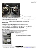
Filter requires replacement if appropriate LED on control panel illuminates (and beeper sounds for 2 seconds every 4 hours).
Filter replacement is ALSO required if you notice the following:
a)
If you are losing suction capacity, after filter has been used…..
FILTER IS CLOGGED
;
b)
If dust is coming through the filter and dust is present in the motor section even though filter is seated properly……..
FILTER IS PUNCTURED
;
c)
Gasket on BASE of HEPA Filter is even slightly worn,
GASKET NEEDS TO BE IN GOOD CONDITION TO ENSURE DUST DOES NOT GET THROUGH
ANNUAL GENERAL INSPECTION
Sealing integrity is essential. Every 12 months, verify all gaskets are in proper condition. Should the door gaskets adhere slightly to the unit when opening a
door, lubricate its surface with a transparent grease or petroleum jelly. Should unit be moved on occasion, ensure that rubber grommets are tightly fastened.
Disconnect the unit by unplugging the power cord from the wall
,
and access the fan section. Verify that the acoustic insulation is well
fastened to the walls. In the event of a problem, call your authorised distributor for spare parts and replace immediately.


