background image

Quatech USB-to-Serial Adapter User’s Manual l 


Making external connections 

 
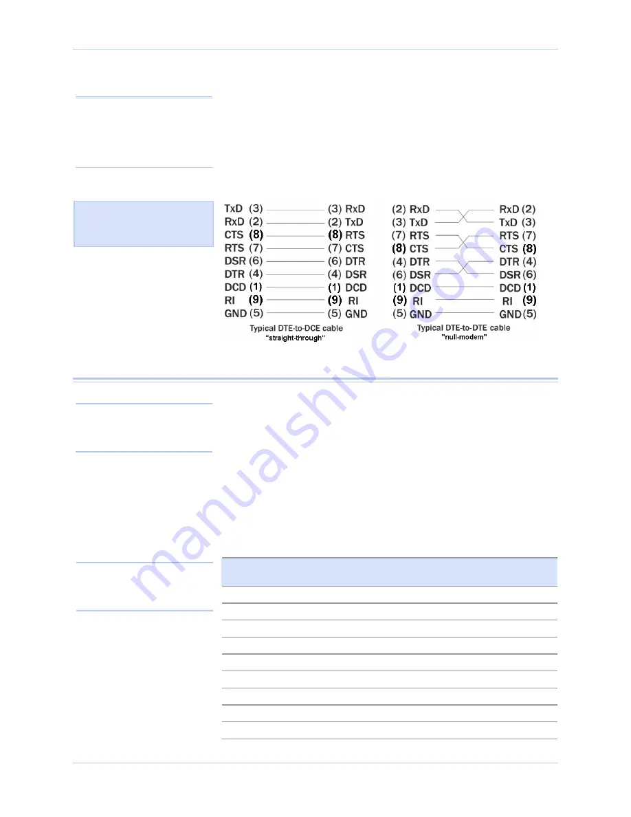
DTE- and DCE-type devices have complementary pinouts that allow 
terminals and modems to connect directly using a one-to-one cable as 

shown in Figure 14.   Two DTE-type devices can be connected by a 

null modem cable.  A typical null modem cable is also shown in the 
figure. 

Note: In many applications, 
DCEs are unnecessary. This 

allows you to use a null modem 
cable (modem eliminator cable) 

to directly connect two DTE-
type devices. 


Figure 14 - Cabling requirements for RS-232 devices 


RS-422/485 serial connections 

Quatech USB-to-Serial adapters provide four differential 
communication signals (either RS-422 or RS-485) per channel. 

Transmit Data (TxD) and Auxiliary Output (AuxOut) are the two 

output signals. Receive Data (RxD) and Auxiliary Input (AuxIn) are 
the two input signals. The adapters also provide a ground signal. 
The AuxOut pair can carry the UART’s RTS signal. The AuxIn pair 

can carry the UART’s CTS signal. Alternatively, the AuxOut pair can 
be configured to internally loopback to the AuxIn pair, with the 

UART’s RTS signal also looped back to its CTS signal.  The following 

table shows the RS-422/485 connector definitions. 

Table 5 - RS-422/485 signals on DB-9 connector 

RS-422/485 signal description 

four-wire mode 

DB-9  RS-422/485 signal description 

two-wire mode 

Auxiliary Input (AuxIn–) 

DNC 

Receive Data (RxD+) 

DNC 

Transmit Data (TxD+) 

Transmit/Receive Data (Data+) 

Auxiliary Output (AuxOut–) 

DNC 

Signal Ground (GND) 

Signal Ground (GND) 

Receive Data (RxD–) 

DNC


Auxiliary Output () 

DNC


Auxiliary Input (AuxIn+) 

DNC


Transmit Data (TxD–) 

Transmit/Receive Data (Data–) 

Note: Pins labeled DNC (Do 

Not Connect) are indeterminate 

in two-wire mode and should be 
left unconnected. 

Note: Refer to Advanced 
Options using Device Manager 

for details on software-
selectable advanced options. 

Figure 14 illustrates the RS-

232 pinouts for typical DTE-
to-DCE and DTE-to-DTE 

cables with 9-pin connectors. 

Rev 1.01  (February 2007) 


Page 13  

Содержание DSU2-100

Страница 1: ...l Parkway Hudson Ohio 44236 5012 Toll free 1 800 553 1170 TEL 330 655 9000 FAX 330 655 9010 http www quatech com SSU2 DSU2 QSU2 ESU2 100 400 User s Manual P N 940 0191 101 USB to Serial Adapter User s Manual SSU2 DSU2 QSU2 ESU2 100 400 1 2 4 and 8 serial ports ...

Страница 2: ...ormation in this manual is believed to be accurate and reliable at the time of posting Notwithstanding the foregoing Quatech assumes no responsibility for any damage or loss resulting from the use of this manual and expressly disclaims any liability or damages for loss of data loss of use and property damage of any kind direct incidental or consequential in regard to or arising out of the performa...

Страница 3: ...under Windows 2000 or Windows XP 11 Making external connections 12 RS 232 serial connections 12 RS 422 485 serial connections 13 Testing DB 9 serial ports in HyperTerminal 14 Running Hyperterminal 14 Using Device Manager 15 Accessing Device Manager 15 Exploring Device Manager screens 15 Windows XP and 2000 15 Setting advanced options 21 Operating Mode MEI adapters only 21 Receiver active MEI adapt...

Страница 4: ...Figure 12 DB 9 connector pinout 12 Figure 13 Use of DTEs and DCEs in a communication link 12 Figure 14 Cabling requirements for RS 232 devices 13 Figure 15 Windows XP 2000 Device Manager properties General tab 16 Figure 16 Windows XP 2000 RS 232 422 485 Advanced Options dialog window 17 Figure 17 Windows XP 2000 RS 232 Advanced Options dialog window 17 Figure 18 Windows XP 2000 USB serial port Por...

Страница 5: ... 422 485 QSU2 100 4 RS 232 QSU2 400 4 RS 232 422 485 ESU2 100 8 RS 232 ESU2 400 8 RS 232 422 485 Note The 400 designation indicates an MEI device MEI is an acronym for Multiple Electrical Interface The interface is software selectable for each serial port Each adapter uses high speed UARTs and deep FIFOs allowing each channel to obtain data rates up to 921 6 kbps The adapters are powered over thei...

Страница 6: ...eaning Red Port is configured for RS 232 Green Port is configured for RS 422 485 IND option surge suppression upgrade Quatech offers an IND option or surge suppression board upgrade to provide improved performance and industrial grade reliability The IND option provides essential protection for reliable use in an industrial environment Each communication line has a surge suppressor capable of sust...

Страница 7: ...ystem in which the device is to be installed Step 2 Plug the wide flat end of the USB cable into the downstream connector This is the connector located on the back of the computer or USB hub Step 3 Plug the square end of the USB cable into the back of the USB to Serial adapter Windows tells you that it has found new hardware and launches the Found New Hardware Wizard Figure 1 Windows XP Found new ...

Страница 8: ...y you can also select the Include this location in the search option and browse to the location with the USB to Serial drivers The complete path is E Serial Port Adapters Drivers Windows 98 Me 2000 XP for USB Replace E with your CD ROM designation Step 7 Click the Next button Windows searches for drivers for the adapter Figure 2 illustrates the Windows XP Choose your search and installation prompt...

Страница 9: ...iption Step 8 The Wizard locates and starts to install the necessary software The Wizard installs the software prompt displays followed by the Finished installing prompt Figure 3 illustrates the Windows XP Searches for drivers prompt When the Wizard finds the USB to Serial drivers this screen disappears Rev 1 01 February 2007 Page 5 ...

Страница 10: ...tware Figure 5 Windows XP Finished installing prompt Step Procedure Description Step 11 Press the Finish button to continue The USB adapter installation is complete Figure 5 shows the Windows XP Finished installing prompt It indicates that the adapter has been successfully installed Page 6 Rev 1 01 February 2007 ...

Страница 11: ...cated on the back of the computer of USB hub Step 3 Plug the square end of the USB cable into the back of the USB to Serial adapter Windows tells you that it has found new hardware and launches the Add New Hardware Wizard The Found new hardware prompt displays Figure 6 Windows 2000 Found new hardware prompt Step Procedure Description Step 4 Click the Next button The Search for or display drivers p...

Страница 12: ...dure Description Step 5 Insert the Quatech installation CD into your CD ROM drive This is the CD that shipped with the adapter Step 6 Select Search for a suitable driver for my device recommended Step 7 Click the Next button The Locate driver files prompt displays Figure 8 Windows 2000 Locate driver files prompt Figure 8 illustrates the Windows 2000 Locate driver files prompt Page 8 Rev 1 01 Febru...

Страница 13: ...ROM drive designation Step 9 Click the Next button Windows searches for drivers for the adapter The Finished searching for driver files prompt displays Figure 9 Windows 2000 Finished searching for driver files prompt Step Procedure Description Step 10 Click the Next button Step 13 The Wizard proceeds with the installation The Please wait while the Wizard installs the software screen displays follo...

Страница 14: ...ished installing prompt Figure 10 is the Windows 2000 Finished installing prompt It indicates that the adapter has been successfully installed Step Procedure Description Step 14 Press the Finish button to continue The USB to Serial adapter installation is complete Page 10 Rev 1 01 February 2007 ...

Страница 15: ...ardware tab 3 Click on Device Manager Figure 11 Device Manager 4 Scroll down to Multi port serial adapters and expand 5 Highlight your Quatech USB to Serial adapter for example ESU2 400 Eight RS 232 422 485 Serial Ports Group ID14 6 Select the Action menu option 7 Select Uninstall from the drop down menu 8 Click OK at the Confirmation screen Note that this also removes all the serial ports associa...

Страница 16: ...CE Figure 13 Use of DTEs and DCEs in a communication link Note A DTE device is the communication source A DCE device provides a communication channel between two DTE type devices Quatech USB to Serial adapters are DTE devices that connect to peripheral equipment through a male DB 9 connector The following table lists the serial port connector definitions Table 4 RS 232 signals on DB 9 connector RS...

Страница 17: ...Out pair can carry the UART s RTS signal The AuxIn pair can carry the UART s CTS signal Alternatively the AuxOut pair can be configured to internally loopback to the AuxIn pair with the UART s RTS signal also looped back to its CTS signal The following table shows the RS 422 485 connector definitions Table 5 RS 422 485 signals on DB 9 connector RS 422 485 signal description four wire mode DB 9 RS ...

Страница 18: ...e to use the correct loopback connector for RS 232 or RS 422 485 Step 2 Launch HyperTerminal In Windows select Programs Accessories Communications HyperTerminal Step 3 Create a new session When prompted give the session any name you wish Step 4 Select the COM associated with port 1 from the drop down list You are now set up to test the first serial port Note Leave all settings at default Step 5 Wi...

Страница 19: ...erty dialogs that apply to the USB to Serial adapter Ports COM LPT device group property box Multi port serial adapters device group property box Use the Ports COM LPT device group property box to view and set the port settings and to view device usage and driver information for the serial ports Use the Multi port serial adapters device group property box to view and set the advanced options and t...

Страница 20: ... General tab Step Procedure Description Step 3 Click the USB Serial Ports Advanced Options tab to view the port setting properties The Advanced Options dialog box displays Figure 15 illustrates the Windows XP 2000 General Tab which tells you whether the USB to Serial adapter is working properly Page 16 Rev 1 01 February 2007 ...

Страница 21: ...ws XP 2000 RS 232 422 485 Advanced Options dialog window Figure 16 illustrates the Advanced Options dialog for MEI devices Figure 17 Windows XP 2000 RS 232 Advanced Options dialog window Figure 17 illustrates the Advanced Options dialog for RS 232 only devices Rev 1 01 February 2007 Page 17 ...

Страница 22: ... expand the Ports COM LPT device group The ports associated with the USB to Serial adapter should appear in the list of ports Step 7 Double click the desired port The USB Serial Port Properties dialog box opens and displays the General tab Step 8 Click the Port settings tab The Port Settings dialog box displays Figure 18 Windows XP 2000 USB serial port Port settings box Step Procedure Description ...

Страница 23: ...rt whose settings you wish to change Click Cancel to return to the Port Settings tab Step 12 Click the Driver tab to view the driver information and update the driver The USB Serial Driver properties dialog box displays Figure 20 Windows XP 2000 USB serial port properties Driver box Step Procedure Description Step 13 You have several options Figure 20 illustrates the USB Serial Ports Driver dialog...

Страница 24: ...ation The Driver File Details dialog box opens See the following figure Figure 21 Windows XP 2000 USB serial port Driver file details box Step Procedure Description Step 15 The Driver File Details dialog box displays the following information Provider File version Copyright Digital Signer Windows XP only Click OK to return to the Driver tab Quatech is the provider This is the version of the instal...

Страница 25: ...tive in this mode This mode allows simultaneous transmit and receive operation Transmit and receive data move over separate dedicated pairs of conductors in the attached cable The AuxOut AuxIn signals are also available in 4 wire mode Note The serial port s LED will glow green in RS 422 485 mode RS 422 485 Half Duplex 2 wire Auto Toggle This mode configures the serial port to use an RS 422 485 ele...

Страница 26: ...rial port to use an RS 422 485 electrical interface This mode operates the same as Half Duplex using RTS except that the UART s DTR output is used Note The serial port s LED will glow green in RS 422 485 mode Receiver active MEI adapters only In RS 422 485 half duplex operating modes the serial port s receivers can be set to be active all the time or to be active only when the port is not transmit...

Страница 27: ...ut are routed to the AuxOut and AuxIn signal pairs respectively Low Latency Mode Low latency mode is an optional setting that disables most data buffering in the device to reduce delays in reporting received data Unchecked default Leave the box unchecked for excellent performance in most applications It is the best balance of performance and responsiveness The serial port can make use of a deep da...

Страница 28: ...ot connected correctly 1 Check all cables to make sure that they are connected correctly 2 Make sure that each cable is securely attached The device driver is not installed 1 Double check the Device Manager per the instructions in Using Device Manager to ensure that drivers are installed correctly and that all devices are working properly 2 Try uninstalling the USB adapter from the Device Manager ...

Страница 29: ...ers Custom high speed UARTs with 1024 byte FIFOs for both transmit and receive Automatic hardware and software flow control Transceivers SSU2 100 DSU2 100 QSU2 100 ESU2 100 RS 232 Output Voltage Swing 5V min 5 4V typical RS 232 Input Voltage Range 15V min 15V max Input Threshold Low 0 6V min 1 0V typical Input Threshold High 2 4V max 1 5V typical Transceivers DSU2 400 QSU2 400 ESU2 400 RS 232 see ...

Страница 30: ...H DSU QSU 9 18 L x 5 25 W x 2 363 H ESU Power Requirements USB bus powered no external power connection required Suspend Power 500 uA Unconfigured Power 100 mA Configured Power 500 mA Temperature Operating 0 to 70 C Storage 50 to 80 C Humidity 10 to 90 OS Support Windows 2000 Windows XP Windows Vista Linux Page 26 Rev 1 01 February 2007 ...

Страница 31: ...rranty repair MUST be assigned a Returned Material Authorization RMA number prior to shipment This RMA number must be clearly marked on the exterior of the product s return packaging and in any correspondence to ensure proper routing and prompt attention To obtain an RMA number contact Quatech Technical Support Department at 1 800 553 1170 or 330 655 9000 In order to prevent damage to returned mer...

Отзывы: