MITX-V1K0 Series - User Guide, Rev. 1.0
// 50
7.15.
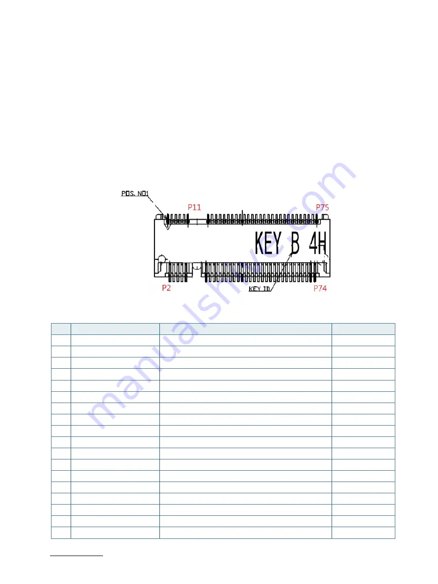
M.2 Socket (M2B1, M2M1 & M2M2)
The MITX-V1K0 Series supports up to three M.2 modules: one in format 2242 / 2280 with Key B and the other two in
format 2280 with Key M.
The M.2 Key B socket (M2B1) shares the same PCIe x2 signals with the PCIe x2 slot (PCIE1). The default assembly
configuration is the M.2 Key B socket M2B1. The specifications supports USB 2.0 and PCIe x2 / PCIe x1 + USB 3.0
(default assembly configuration is PCIe x2) signals as well as a SIM card socket. The SIM card socket makes it possible
to use a WWAN wireless modem in this M.2 socket.
The M.2 Key M sockets (M2M1 & M2M2) supports SATA signals. They share the same SATA signals with the SATA
connectors (SATA1 & SATA2 respectively). The default assembly configuration is the M.2 Key M socket M2M2 and
SATA connector SATA1.
Figure 30: M.2 Key B Slot Connector M2B1
Table 37: Pin Assignment M2B1
Pin
Signal
Description
Note
1
NC
2
+3.3V
+3.3 V power supply
3
GND
Ground
4
+3.3V
+3.3 V power supply
5
GND
Ground
6
M2B_ PWROFF#
M.2 module power off active low
7
USB-D+
USB 2.0 differential pair (+)
8
M2B_WDIS1#
Wireless disable signal
9
USB-D-
USB 2.0 differential pair (-)
10
M2B_LED1#
Device active signal
11
GND
Ground
12
KEY B
13
KEY B
14
KEY B
15
KEY B
16
KEY B
17
KEY B
18
KEY B


