


MITX-V1K0 Series - User Guide, Rev. 1.0
// 40
7.8.
Front Panel Pin Header (FP1 & FP2)
The front panel connector FP1 supplies signals for the reset button, storage LED and system warning speaker.
The front panel connector FP2 supplies signals for the power button, power LED and SM Bus.
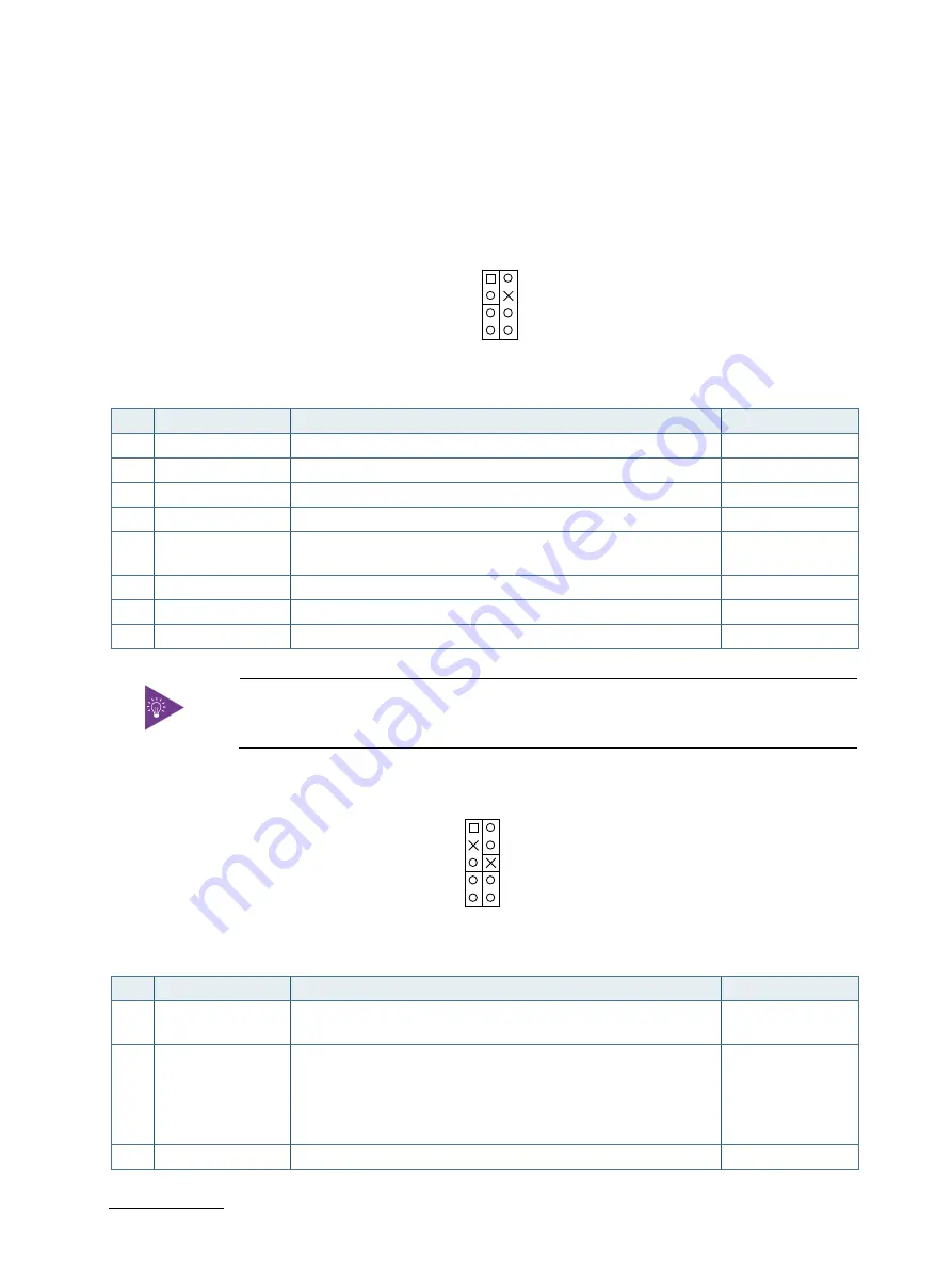
Figure 22: Front Panel 1 Pin Header FP1
Table 27: Pin Assignment FP1
Pin
Signal
Description
Note
1
Reset
System reset button (+)
2
S
External system warning speaker (+)
3
Reset Button -
System reset button (-)
4
NC
No connection
5
HDD LED +
HDD activity LED (+). The LED lights up or flashes when data is
ready from or written to the HDD.
6
Internal Speaker - Internal system warning speaker (-)
7
HDD LED -
HDD activity LED (-).
8
Speaker -
External system warning speaker (-)
Internal Buzzer is enabled when Pin6-8 is shorted.
Figure 23: Front Panel 2 Pin Header FP2
Table 28: Pin Assignment FP2
Pin
Signal
Description
Note
1
Power LED +
System Power LED (+). The LED lights up when users turn on the
system power, and blinks when the system is in sleep mode.
2
Power
System power button (+). Pressing the power button turns the
system on or puts the system in sleep or soft-off mode
depending on the operating system settings. Pressing the
power switch for more than four seconds while the system
turns from ON to OFF.
3
NC
No connection
-
+
SPKR
+
7
8
HLED
2
1
-
+
RSTBTN
-
+
KLOCK
PLED
2
-
-
9
+
SMC
-
SMD
10
+
1
PWRBTN


