background image

June 18, 2014   


           7082-132C 


                  13

MT. VERNON E2 INSERT

Remote Thermostat: Fahrenheit / Celsius

1.  Temperatures will show either °F or °C displayed on the 

screen.

2.  Press both “UP” and “DOWN” arrow keys simultane-

ously. 

The display should change from Fahrenheit to 

Celsius or vice-versa.

Remote Thermostat: Swing

1.  The swing temperature will allow over-target of the 

set point temperatures set while in “THERMO” mode.  
Example, if the set point temperature is 70°F and swing 
is ±2° the appliance will not go into a shutdown until it 
reaches 72°F.  Likewise, the appliance will not startup 
unless it is below 68°F.

2.   To change the temperature “SWING” setting (1°-3°), 

press the TIMER and DOWN buttons simultaneously to 
display the current “SWING” setting in the SET TEMP 
frame. 

3.  The letter “S” will display in the ROOM TEMP frame on 

the screen.

4.  Press the UP or DOWN button to change the tempera-

ture differential (from 1º to 3º).

5.  To store the “swing number press the MODE/SET 

button or allow 15 seconds to lapse, and the new 
“swing number’ will be programmed.

6.  To verify that the swing is properly set, and with the 

appliance dial control set to “OFF” & remote thermostat 
set to “THERMO”, raise and lower the temperature 
above and below the room temperature to identify its 
response. This should change from THERMON to 
OFFTHERMO.

Remote Thermostat: Child Lockout feature

1.  To activate the “LOCK-OUT” feature, press and hold 

the UP button and touch the word TIMER on the screen 
of the transmitter together, for 5 seconds.  The lock 
icon will appear on the screen.

2.  To disengage the “LOCK-OUT”, press and hold the 

UP button and touch the word TIMER on the screen 
together for 5 seconds or more, and the lock icon will 
disappear from the screen. The transmitter will return to 
its normal operating condition.

Note:   If the appliance is already operating in the ON or 
THERMO MODES, engaging the “LOCK-OUT” will not 
cancel the operating MODE.  Engaging the “LOCK-OUT” 
prevents only the manual operation of the TRANSMITTER.  
If in the auto modes, the THERMO operation will continue 
to operate normally.  To completely “LOCK-OUT” the opera-
tion of the TRANSMITTER’S operating signals; the trans-
mitter’s MODE must be set to OFF.

Remote Thermostat: Signal

1.  The remote thermostat sends a signal to the receiver 

every 15 minutes verifying the transmitter is still in 
range.

2.  If the remote thermostat falls out of signal range or has 

no battery power for over 2 hours or has no battery 
power the receiver will emit a communication Safety 

Error Code consisting of a series of rapid “beeps” for 
a period of 10 seconds and the appliance will shut 
down.  After 10 seconds of rapid beeping, the receiver 
will continue to emit a single “beep” every 4 seconds 
until the remote thermostat MODE button is pressed, 
resetting the receiver.  

Note: Unless damaged or remote component is replaced 
the receiver will maintain its communication link to its trans-
mitter for many years.

Remote Trouble Shooting

1.  Make sure the remote thermostat’s batteries are prop-

erly installed.

2.  Check to make sure the thermostat is communicating 

with the receiver (an audible sound from the receiver 
should emit when changing from “OFF” to “ON”).

3.  If the receiver does not beep when changing from OFF 

to ON, you will need to “LEARN” the receiver to the 
remote thermostat.  (See Learning the remote thermo-
stat to receiver section).  

4.  Make sure the remote thermostat is within the 15 to 

20-foot range of the receiver.

R. Bypassing the Remote System (Manual 
Mode)

1.  If the remote thermostat is lost, broken, or loses its 

power the appliance can be operated in manual mode.

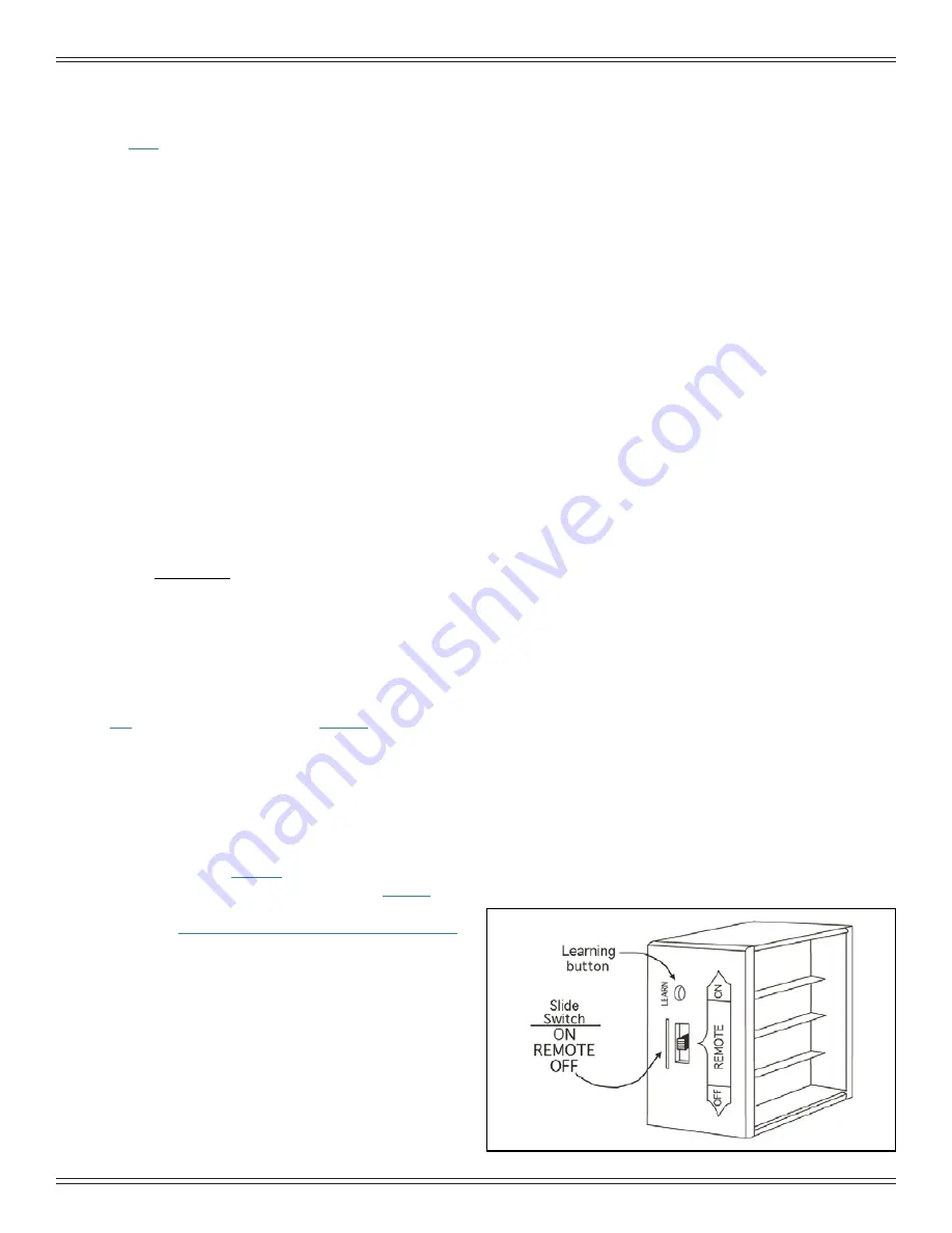
2.  Locate the three-way switch on the receiver. 

Figure 

13.1

3.  Placing the receiver three-way switch to “ON” will 

bypass the remote thermostat function, rendering the 
appliance dial control as its exclusive control. 

4.  The appliance will not run when the switch is set to 

“OFF”. 

Location of the Remote Receiver:
The receiver face can be seen when the front RH cast 
panel is removed.

Note: Placing the receiver three-way switch in the 
“REMOTE” or center-most position empowers the remote 
system.

Figure 13.1

Содержание MTVI-E2-CSB

Страница 1: ...Keep clothing furniture draperies and other flammable materials away WARNING CAUTION Tested and approved for wood pellets only NOTE To obtain a French translation of this manual please contact your de...

Страница 2: ...fil lectrique au dessus ou en dessous de l appareil Ne pas bloquer l espace au dessous de l appareil DANGER Il y a risque de d charge lectrique D connectez le fil lectrique de la prise de contact ava...

Страница 3: ...ety 8 B Non Combustible Materials 8 C Combustible Materials 8 D Fuel Material and Fuel Storage 8 E Before Your First Fire 9 F Filling the Hopper 9 G User Dial Control 9 H Normal Startup Sequence 9 I F...

Страница 4: ...uction warranty coverage begins on the date of first occupancy of the dwelling or six months after the sale of the product by an independent authorized HHT dealer distributor whichever occurs earlier...

Страница 5: ...T VERNON E2 INSERT WARRANTY CONDITIONS This warranty is void if LIMITATIONS OF LIABILITY 8 K N N OQ R U Z 8 88 U 8 U Q 8 N N Q Z R N U Q 8 R Z N N 88 N U Q 8 N O K WARRANTY EXCLUSIONS N Z N _ q _ q _...

Страница 6: ...pellets will feed Wait for 2 minutes If the LIGHT did not turn solid green Turn dial back to OFF Unplug appliance plug it back in and repeat Priming is only needed for first fire or starting fire on...

Страница 7: ...ies Installation and or use of any component part not approved by Hearth Home Technologies Operating appliance without fully assembling all components Operating appliance without legs attached if supp...

Страница 8: ...e from sawdust or wood by products Depending on the source material it may have a high or low ash content Higher Ash Content Material Hardwoods with a high mineral content Fuel that contains bark Stan...

Страница 9: ...happens the smoke should quickly disap pear During this stage as well as any part during the burn process the front door should not be opened HEAT SETTING HEAT SETTING O F F HI LO This startup cycle...

Страница 10: ...tial operation Curing of high temperature paint Open windows for air circulation Odors may be irritating to sensitive individuals CAUTION WARNING HOT SURFACES Glass and other surfaces are hot during o...

Страница 11: ...or in shutdown During shut down the blowers will shut off when the exhaust temperature has cooled Green 1X Stage 1 Low heat BTU Range 1 8653 19 694 Average 19 054 Green 2X Stage 2 Med Low heat BTU Ra...

Страница 12: ...r the unit may have too much air To decrease the amount of combustion air rotate the trim dial towards zero one level at a time and allow 15 minutes for stabilization prior to making another adjustmen...

Страница 13: ...manual operation of the TRANSMITTER If in the auto modes the THERMO operation will continue to operate normally To completely LOCK OUT the opera tion of the TRANSMITTER S operating signals the trans m...

Страница 14: ...the Non burn season see troubleshooting section Is there a place to lubricate the blowers to quiet them down No The most often cause of noisy blowers is from the impellers becoming dirty over time Se...

Страница 15: ...ce for your appliance Visit www quadrafire com to locate a dealer We recommend annual service by a qualified dealer A Proper Shutdown Procedure Turn dial control to OFF let appliance completely cool a...

Страница 16: ...cleaned out more often than ash Ash Disposal Ashes should be placed in a steel container with a tight fitting lid The container of ashes should be moved outdoors immediately and placed on a non combus...

Страница 17: ...re to vacuum the back of the baffle also Inspect the drop tube and remove any residue build up in the drop tube Figure 17 3 c Assemble the crevice tool from the micro cleaning kit to attach to a Shop...

Страница 18: ...he appliance is allowed to cool b Open the front cast door and cycle the ash removal handle these should be inspected for functionality c Inspect for any degradation or deformation As the springs heat...

Страница 19: ...he glass and firebox should be inspected periodically to make sure there is a good seal If the gasket is frayed or damaged replace with a new one 8 Cleaning Exhaust System Requires No Lubrication Freq...

Страница 20: ...mation on how to handle a chimney fire In the event of a soot or creosote fire close the firebox door exit the building immediately and contact the proper fire authorities DO NOT under any circumstanc...

Страница 21: ...2 5 Rock the top of the blower slightly and lift up The blower will pass out the left side of the appliance Note You may need to loosen the surround to move it out of the way 6 Install replacement blo...

Страница 22: ...p disc is tripped Check to make sure convection blower wires are connected and reset snap disc located on RH side of appliance Clean inspect convection blower and convection air path Feed System is ja...

Страница 23: ...er fails to shut off Wire short between blower and ground Control board is defective Repair wire and replace control board Exhaust blower fails to start and or red flashes 6X indicating a exhaust enco...

Страница 24: ...t trim per trim dial instructions Feed Motor locked on Follow corrective action for feed motor not turning off Excessive fuel spilling over the fire pot and or excessive flame Dirty Appliance Clean un...

Страница 25: ...terminal end to control board Failed component Replace exhaust probe securing it to exhaust blower housing keeping wire away from hot surfaces 4 Red Flashes Missed Ignition Hopper empty Fill the hopp...

Страница 26: ...Convection Blower The convection blower is mounted at the bottom left of the appliance The convection blower pushes heated air through the heat exchange system into the room 4 Feed System The feed sy...

Страница 27: ...ON INSERT E2 Beginning Manufacturing Date Dec 2014 Ending Manufacturing Date Active Pellet Insert MTVI E2 CSB MTVI E2 MBK MTVI E2 PMH Part number list on following pages 11 13 40 39 38 37 36 35 34 33...

Страница 28: ...06P 3 Top Matte Black 7036 101MBK Porcelian Mahogany 7036 101PMH Sienna Bronze 7036 101CSB 4 Catch Clip 7036 146 5 Elbow Catch 7000 393 6 Bracket Catch 7036 145 7 Backer Side Window 414 0280 8 Side Ma...

Страница 29: ...ner 7034 136 19 2 Glass Assembly 21 W x 14 H 7034 007 Y 19 3 Hinge Female 450 2910 19 4 Door Latch Assembly 413 5200 Gasket Channel 3 Mm X 32 Field Cut to Size 10 Ft 7000 377 10 Y 20 Ash Pan Door 7034...

Страница 30: ...Blower SRV7080 106 Y Gasket Blower Combustion Between Housing Stove SRV7080 117 Y Gasket Motor Blower Combustion Between Housing Motor SRV7080 107 Y 32 Snap Disc L250 Manual Reset SRV230 1290 Y 33 Fl...

Страница 31: ...B Y Outside Air Kit OAK 3 Top Vent Adapter TPVNT 3 Vent Adapter 3 4 811 0720 Vent Adapter 90 cleanout TPVNT 6 Vent Adapter Cleanout 811 0620 Surround Std Panel For Cast Trim SP MTVS CST Component Pac...

Страница 32: ...ille WA 99114 Division of HNI INDUSTRIES Please contact your Quadra Fire dealer with any questions or concerns For the number of your nearest Quadra Fire dealer log onto www quadrafire com This produc...

Отзывы: