5
Installation
Free-standing Installation
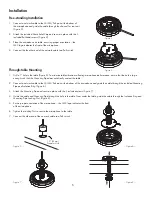
1. Connect a network cable to the Q-LAN/PoE port at the bottom of
the microphone and guide the cable through the channel for rear exit
(Figure 3).
2. Attach the included Strain Relief Cap and secure in place with the 3
included flat head screws (Figure 4).
3. Place the microphone on table, ensuring proper orientation – the
QSC logo indicates the front of the microphone.
4. Connect the the other end of the network cable to a PoE switch.
Through-table Mounting
1. Drill a 1” hole in the table (Figure 5). To minimize table vibrations affecting microphone performance, ensure that the hole is large
enough such that the Mounting Pipe does not directly contact the table.
2. Connect a network cable to the Q-LAN/PoE port at the bottom of the microphone and guide the cable through the included Mounting
Pipe and Isolation Ring (Figure 6).
3. Attach the Mounting Pipe and secure in place with the 3 included screws (Figure 7).
4. Guide the cable and Mounting Pipe through the hole in the table. From under the table, guide the cable through the Isolation Ring and
Mounting Pipe Locking Nut. (Figure 8).
5. Ensure proper orientation of the microphone – the QSC logo indicates the front
of the microphone.
6. Tighten the Locking Nut to secure the microphone to the table.
7. Connect the other end of the network cable to a PoE switch.
— Figure 3 —
— Figure 4 —
1.0” [25mm]
Diameter Hole
— Figure 5 —
— Figure 6 —
— Figure 7 —
— Figure 8 —


