QSC III Series Скачать руководство пользователя страница 26


26


Unstable 

Signal is usually distorted, fuzzy or shows a smeared scope trace, usually worse on some part of the waveform. Do 
not confuse this with hum in the signal, which evenly spreads trace vertically. Distinguish between the two by 
reducing the sweep rate to a 10ms range, use an AC/line trigger, and look for 60-120 Hz hum frequencies. 

1.  Possible causes of severe instability, often with current draw: 

a.  Slew rate capacitor, C3, and R10 are missing or measure too low 
b.  Feedback capacitor, C2, is missing or measures too low 

2.  Possible causes of medium instability, especially with a light load: 

a.  The stability capacitor value is too high; check feedback capacitor C2, secondary stability 

capacitors, C9 and C10 

b.  R10 is the wrong value 

3.  If gain is very low, suspect open circuit in feedback shunt, R8 and E4, or broken circuit trace. 
4.  Also, substitute the IC and check the IC socket for contamination 


Wrong Current Limits 

1.  If the current is too high into a shorted output and the IC rails measure normal (5-6 volts), check for 

a.  A reversed or shorted 3.9V or 4.7V zener diode (Z15 or Z16) 
b.  Shorted bias diode, D5 or D6 (shows severe crossover) 

2.  If the current is too high into a shorted output and the IC rail measures too high during the short, some 

possible causes are: 

a.  A bad IC (has weak output current) 
b.  Does the clip LED work? If not, the clip LED, LD2, could be open, the clip circuit part, R11 

could be missing or measure too high or B1 could be defective 

c.  Check for short circuit current balance by raising the scope gain during a short and looking at 

the small voltage across the residual short resistance. Concentrate on parts and circuits 
connected to the side with the high current if unbalanced (remember the reverse polarity of the 
QSC circuit, see below). 

3.  If the current is too low into a shorted output as well as a 2 ohm load, check: 

a.  If the IC rails are o.k. some possible causes are: 

i.  Bias resistor R19 or R22 measures too high 

ii.  Very low gain resistors (see below) 

4.  If the current is too low into a short only and is normal into typical loads: 

a.  Check whether the clip LED, LD2 is shorted, 1.5A rectifier, B1, is shorted or R11 is too low 
b.  Check whether the 3.9V or 4.7V zeners, Z15 or Z16, are too high (i.e. 7.5V or 15V respectively) 

5.  If the current is normal into a short but low into 2 ohms (usually on one side only), check 

a.  If IC rail is too low (driving two ohms even before clipping, 

i.  Check for high or missing chargeback resistor, R52, or missing or reversed chargeback 

diode, D8 or D9 (usually causes premature clipping at 4 ohms as well) 

b.  If IC rail is o.k. (at least until clipping starts), 

i.  This could indicate low gain above or below the step (see Driver Gain Section below) 

ii.  Check if all the high voltage outputs (Q8, Q9, Q10 and Q14, Q15, Q16) and emitter 

resistors (R38, R39, R40, and R44, R45, R46) are good; otherwise, it’s possible that 
the upper driver has very low gain (see next section) 


Step Problems 

These are troubles associated with the circuit switching from the 50% rail to the 100% rail. Normal performance 
allows about 0.03-0.05% extra distortion which can be seen when measuring into 4 or 8 ohm loads at 20kHz. Watch 
for instability or spikes at the step, or weak output above the step. 

1.  If the output stops at the step, even into no load, check for 

a.  Missing or reversed D12 or D15 

2.  If the output steps correctly with an 8 ohm load but is weak or hesitant with a 2 or 4 ohm load, check for 

a.  A missing Q23, D11, R57 or Q22, D14, R58 
b.  A reversed Q22 or Q23 

3.  To test the driver gain and step circuit: 

a.  Turn the gain knobs up until the output of the amp is at the threshold of clipping. 
b.  If one side clips too early, the circuit of the opposite polarity has the problem (this is a usual 

feature of QSC amplifier designs). 

Содержание III Series

Страница 1: ...Series III Power Amplifiers TECHNICAL SERVICE MANUAL 3800 R E V B TD 300001 AX 3500 3350 3200...

Страница 2: ...Power Amplifiers QSC Audio Products Inc Technical Services Group Toll Free 800 772 2834 Local 714 957 7150 Fax 714 754 6173 QSC Audio Products Inc 1675 MacArthur Blvd Costa Mesa CA 92626 www qscaudio...

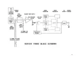
Страница 3: ...3 SERIES THREE POWER AMPLIFIERS...

Страница 4: ...Diagram 18 Detailed Explanations 18 Troubleshooting Chart 23 Introduction 23 1 Current Draw Section 23 2 Protection Circuit Problems 24 3 Faults With Signal Present 25 Series Three Test Procedures 29...

Страница 5: ...d in parallel 2 terminal barrier strip and 5 way binding post outputs wired in parallel octal input sockets provided for input transformers or active accessories ground lift terminal block Cooling Pas...

Страница 6: ...allel 2 terminal barrier strip and 5 way binding post outputs wired in parallel octal input sockets provided for input transformers or active accessories ground lift terminal block Cooling Passive coo...

Страница 7: ...s wired in parallel 2 terminal barrier strip and 5 way binding post outputs wired in parallel octal input sockets provided for input transformers or active accessories ground lift terminal block Cooli...

Страница 8: ...signal level indicators flashing over temp indicators Cooling Passive cooling combined with high efficiency output stage for 50 reduction in dissipated heat Unique circuit configuration provides dire...

Страница 9: ...BP 001UF 100V 10 MYLAR C1 C9 D9 D18 C10 C15 QD 004410 TX BJTN 80V 25A 1 5W 2N4410 Q9 Q13 CA 222100 BP 0022UF 100V 10 MYLAR C3 Q14 CA 347050 BP 047UF 50V 10 MYLAR C7 C8 QD 004744 ZA ZENER 15V 1W 5 1N4...

Страница 10: ...BC 5 1K 1 4W 5 CF R6 RE 210001 BM RESISTOR MF 10 OK 1 1 4 R1 R2 R3 R4 RE 212101 CM 12 1K 1 2W 1 MF R7 RE 210005 BC 10K OHM 1 4W CARBON 5 R45 RE 230005 BC 30K 1 4W 5 CF R46 RE 242201 BM RESISTOR 42 2K...

Страница 11: ...DGE RECT QD 0003 9 ZT ZENER 3 9V 25W DZ84073ID Z15 PL 003 65 TW TIE WRAP 4 BLACK SMALL QD 0004 7 ZT ZENER 4 7V 25W DZ840731E Z16 PL 000011 TW TIE WRAP 11 WHITE LONG QD 0007 5 ZT ZENER 7 5V 25W DZ84073...

Страница 12: ...CF R11 R20 R21 R61 RE 010005 CC 100 1 2W 5 CF R32 RE 033201 BM 332 1 4W 1 MF R8 RE 033005 HW 330 OHM 5 WATT WW 10 R52 RE 015005 BC 150 1 4W 5 CF R57 R58 RE 110005 BC 1K 1 4W 5 CF R5 RE 110005 EM 1K 2...

Страница 13: ...ULATOR D21 D22 LB 100003 SR ON SUBPANEL PL 903125 SP SPACER ROUND NYLON 0 047 L1 L2 LB 376002 MP ON SUBPANEL R14 MS 350410 HS HEAT SINK PL 905385 SP SPACER RND NYL 6 0 385 L B LD1 LD2 MS 350472 SP SUB...

Страница 14: ...000050 NR NTC THERMISTOR 50 OHM R14 RE 001005 EM 10 2W 5 MOFP R56 RE 002205 DM 22 1W 5 MOFP R15 R16 R17 R18 RE 010005 BC 100 1 4W 5 CF R11 R20 R21 R61 RE 018005 CC 180 1 2W 5 CF R32 RE 033201 BM 332...

Страница 15: ...NW 060410 ST A 4 SPRING TOOTH LOCKWASHER P NW 060400 HN 6 32 BY 1 4 HEX NUT P D5 D6 PC 000046 AM MAIN NPN BOARD PL 000220 MI D5 D6 PL 905100 SP SPACER ROUND NYLON 6 0 L1 L2 PT 250000 AT RES VAR IT 5K...

Страница 16: ...M 6 8 OHM 1W MET OXIDE 5 R13 NW 060410 ST LCKWSHR ON HEAT XFER BRKT MTG PEMS RE 247005 BC 47K 1 4 W 5 CF R11 NW 060400 HN 6 32 BY 1 4 HEX NUT PEMS RE 210005 BC 10K OHM 1 4W CARBON 5 R2 R12 PC 000047 B...

Страница 17: ...BG GAIN PCB BOARD PL 905385 SP SPACER RND NYL 6 0 385 L B LD1 LD2 LD3 LD4 LD5 PL 909235 SP HOLDER LED 90 DEGREES NY LD1 LD2 LD3 LD4 LD5 QD 000134 LR LED RED T 1 3 4 LD1 LD2 QD 000134 LX LED R G T 1 3...

Страница 18: ...e power supplies are DC coupled with the usual transformer center tap We use a speaker relay for DC protection as discussed in section 6 The second unusual feature is that we reverse the usual locatio...

Страница 19: ...ermined by the base current to each driver through 1K resistors and 3 9V zener diodes R19 and R22 Z15 and Z16 When the op amp rails are at their normal 15V this current is about 9ma and results in abo...

Страница 20: ...an at full output By having a lower level DC supply for lower levels of output voltages up to 50 we greatly reduce waste voltage and power for lower level signals Of course the big problem is to switc...

Страница 21: ...2V This is enough to forward bias the bridge rectifier B2 and turn on Q19 Note that Q19 is connected to the rectifier so that either polarity of DC will trigger it When Q19 turns on it discharges E7...

Страница 22: ...22...

Страница 23: ...r pins a hard short solder short will read virtually zero volts A reading of 0 6 1V above ground indicates a reversed diode or shorted output A reading of 1 2 volts could mean a bad driver but outputs...

Страница 24: ...is enough to activate zener diode Z17 which turns off the base of Q18 which is at 2 2V when on and shuts off the relay circuit The latching effect holds the circuit off until the PTC voltage has coole...

Страница 25: ...too small of a resistance a low voltage on E7 turns Q18 on too soon d Missing or too large of a resistance at R30 no off current 3 Possible causes of an excess muting delay a Check the voltage across...

Страница 26: ...the current is too low into a shorted output as well as a 2 ohm load check a If the IC rails are o k some possible causes are i Bias resistor R19 or R22 measures too high ii Very low gain resistors se...

Страница 27: ...an indicate a problem in minor stability components see that section above b Also check the output filter R56 L2 R49 R50 C5 and inner coil R55 and L1 c Alternatively the crossover or step may be large...

Страница 28: ...s bad d Possible causes of high frequency distortion i The value of C3 is too high x10 for the slew rate compensation capacitor ii The base resistors R15 R16 R17 or R18 on the output devices are missi...

Страница 29: ...visible on the positive and negative halves of the waveform still into no load on channel B of the oscilloscope d Switch the load to 8 ohms and vary the amplifier gain just above and below the step sw...

Страница 30: ...2 output and observe power output at 20Hz 0 5dB max and 20kHz 0 5dB max 10 Temperature cycle a Switch to the 2 6 ohm load Increase the signal to the point of clipping and short the output of the ampli...

Страница 31: ...isible on the positive and negative halves of the waveform still into no load on channel B of the oscilloscope d Switch the load to 8 ohms and vary the amplifier gain just above and below the step swi...

Страница 32: ...or 9 5dB output and observe power output at 20Hz 0 5dB max and 20kHz 0 5dB max 10 Temperature cycle a Switch to the 2 ohm load Increase the signal to the point of clipping and short the output of the...

Страница 33: ...sible on the positive and negative halves of the waveform still into no load on channel B of the oscilloscope d Move the wiring harness and tap the circuit boards with a non conductive implement such...

Страница 34: ...r Select a 2kHz signal input to the amplifier b Adjust the amp gain to obtain 215 watts x2 or 7 5dB output and observe power output at 20Hz 0 5dB max and 20kHz 0 5dB max 10 Temperature cycle a Switch...

Страница 35: ...veform still into no load on channel B of the oscilloscope d Switch the load to 8 ohms and vary the amplifier gain just above and below the step switching level Watch for obvious step oscillation This...

Страница 36: ...0W x 2 10 Temperature cycle a Switch to the 2 ohm load Increase the signal to the point of clipping and short the output of the amplifier The clip LED should be on Check for recovery into 2 ohms cold...

Страница 37: ...Series Three Schematics Model3200...

Страница 38: ...Model 3350...

Страница 39: ...Model 3500 Early Version...

Страница 40: ...Model 3500 Late Version...

Страница 41: ...Model 3800...

Страница 42: ...Series Three PCB Drawings Model 3200 PCB...

Страница 43: ...Model 3350 PCB...

Страница 44: ...Model 3800 46A PCB...

Страница 45: ...Model 3800 47A PCB...

Страница 46: ...Model 3800 48B PCB...

Страница 47: ...Model 3800 Gain PCB...

Страница 48: ...QSC Audio Products Inc 1675 Mac Arthur Blvd Costa Mesa CA 92626 Tel 714 754 6175 Fax 714 754 6173...

Отзывы: